
规范一:《GB 50736-2012 民用建筑供暖通风与空气调节设计规范(含条文说明)》
3.0.6 设计最小新风量应符合下列规定:
1 公共建筑主要房间每人所需最小新风量应符合表 3.0.6-1 规定。
表 3.0.6-1 公共建筑主要房间每人所需最小新风量[m³/(h·人)]
| 建筑房间类型 | 新风量 |
|---|---|
| 办公室 | 30 |
| 客房 | 30 |
| 大堂、四季厅 | 10 |
3 高密人群建筑每人所需最小新风量应按人员密度确定,且应符合表 3.0.6-4 规定。
表 3.0.6-4 高密人群建筑每人所需最小新风量[m³/(h·人)]
| 建筑类型 | 人员密度 (P_F) (人/m²) | ||
|---|---|---|---|
| (P_F ≤0.4) | (0.4 < P_F≤1.0) | (P_F > 1.0) | |
| 影剧院、音乐厅、大会厅、多功能厅、会议室 | 14 | 12 | 11 |
| 商场、超市 | 19 | 16 | 15 |
| 博物馆、展览厅 | 19 | 16 | 15 |
| 公共交通等候室 | 19 | 16 | 15 |
| 歌厅 | 23 | 20 | 19 |
| 酒吧、咖啡厅、宴会厅、餐厅 | 30 | 25 | 23 |
| 游艺厅、保龄球房 | 30 | 25 | 23 |
| 体育馆 | 19 | 16 | 15 |
| 健身房 | 40 | 38 | 37 |
| 教室 | 28 | 24 | 22 |
| 图书馆 | 20 | 17 | 16 |
| 幼儿园 | 30 | 25 | 23 |
6 通 风
6.1 一般规定
6.1.1 当建筑物存在大量余热余湿及有害物质时,宜优先采用通风措施加以消除。建筑通风应从总体规划、建筑设计和工艺等方面采取有效的综合预防和治理措施。
6.1.2 对不可避免放散的有害或污染环境的物质,在排放前必须采取通风净化措施,并达到国家有关大气环境质量标准和各种污染物排放标准的要求。
6.1.3 应首先考虑采用自然通风消除建筑物余热、余湿和进行室内污染物浓度控制。对于室外空气污染和噪声污染严重的地区,不宜采用自然通风。当自然通风不能满足要求时,应采用机械通风,或自然通风和机械通风结合的复合通风。
6.1.4 设有机械通风的房间,人员所需的新风量应满足第 3.0.6 条的要求。
6.1.5 对建筑物内放散热、蒸汽或有害物质的设备,宜采用局部排风。当不能采用局部排风或局部排风达不到卫生要求时,应辅以全面通风或采用全面通风。
6.1.6 凡属下列情况之一时,应单独设置排风系统:
- 两种或两种以上的有害物质混合后能引起燃烧或爆炸时;
- 混合后能形成毒害更大或腐蚀性的混合物、化合物时;
- 混合后易使蒸汽凝结并积聚粉尘时;
- 散发剧毒物质的房间和设备;
- 建筑物内设有储存易燃易爆物质的单独房间或有防火防爆要求的单独房间;
- 有防疫的卫生要求时。
6.1.7 室内送风、排风设计时,应根据污染物的特性及污染源的变化,优化气流组织设计;不应使含有大量热、蒸汽或有害物质的空气流入没有或仅有少量热、蒸汽或有害物质的人员活动区,且不应破坏局部排风系统的正常工作。
6.1.8 采用机械通风时,重要房间或重要场所的通风系统应具备防止以空气传播为途径的疾病通过通风系统交叉传染的功能。
6.1.9 进入室内或室内产生的有害物质数量不能确定时,全面通风量可按类似房间的实测资料或经验数据,按换气次数确定,亦可按国家现行的各相关行业标准执行。
6.1.10 同时放散余热、余湿和有害物质时,全面通风量应按其中所需最大的空气量确定。多种有害物质同时放散于建筑物内时,其全面通风量的确定应符合现行国家有关工业企业设计卫生标准的有关规定。
6.1.11 建筑物的通风系统设计应符合国家现行防火规范要求。
6.3 机械通风
6.3.1 机械送风系统进风口的位置,应符合下列规定:
- 应设在室外空气较清洁的地点;
- 应避免进风、排风短路;
- 进风口的下缘距室外地坪不宜小于 2m,当设在绿化地带时,不宜小于 1m。
6.3.2 建筑物全面排风系统吸风口的布置,应符合下列规定:
- 位于房间上部区域的吸风口,除用于排除氢气与空气混合物时,吸风口上缘至顶棚平面或屋顶的距离不大于 0.4m;
- 用于排除氢气与空气混合物时,吸风口上缘至顶棚平面或屋顶的距离不大于 0.1m;
- 用于排出密度大于空气的有害气体时,位于房间下部区域的排风口,其下缘至地板距离不大于 0.3m;
- 因建筑结构造成有爆炸危险气体排出的死角处,应设置导流设施。
6.3.3 选择机械送风系统的空气加热器时,室外空气计算参数应采用供暖室外计算温度;当其用于补偿全面排风耗热量时,应采用冬季通风室外计算温度。
6.3.4 住宅通风系统设计应符合下列规定:
- 自然通风不能满足室内卫生要求的住宅,应设置机械通风系统或自然通风与机械通风结合的复合通风系统。室外新风应先进入人员的主要活动区;
- 厨房、无外窗卫生间应采用机械排风系统或预留机械排风系统开口,且应留有必要的进风面积;
- 厨房和卫生间全面通风换气次数不宜小于 3 次/h;
- 厨房、卫生间宜设竖向排风道,竖向排风道应具有防火、防倒灌及均匀排气的功能,并应采取防止支管回流和竖井泄漏的措施。顶部应设置防止室外风倒灌装置。
6.3.5 公共厨房通风应符合下列规定:
1 发热量大且散发大量油烟和蒸汽的厨房设备应设排气罩等局部机械排风设施;其他区域当自然通风达不到要求时,应设置机械通风;
2 采用机械排风的区域,当自然补风满足不了要求时,应采用机械补风。厨房相对于其他区域应保持负压,补风量应与排风量相匹配,且宜为排风量的 80%~90%。严寒和寒冷地区宜对机械补风采取加热措施;
3 产生油烟设备的排风应设置油烟净化设施,其油烟排放浓度及净化设备的最低去除效率不应低于国家现行相关标准的规定,排风口的位置应符合本规范第 6.6.18 条的规定;
4 厨房排油烟风道不应与防火排烟风道共用;
5 排风罩、排油烟风道及排风机设置安装应便于油、水的收集和油污清理,且应采取防止油烟气味外溢的措施。
6.3.6 公共卫生间和浴室通风应符合下列规定:
1 公共卫生间应设置机械排风系统。公共浴室宜设气窗;无条件设气窗时,应设独立的机械排风系统。应采取措施保证浴室、卫生间对更衣室以及其他公共区域的负压;
2 公共卫生间、浴室及附属房间采用机械通风时,其通风量宜按换气次数确定。
6.3.8 汽车库通风应符合下列规定:
1 自然通风时,车库内 CO 最高允许浓度大于 30mg/m³时,应设机械通风系统;
2 地下汽车库,宜设置独立的送风、排风系统;具备自然进风条件时,可采用自然进风、机械排风的方式。室外排风口应设于建筑下风向,且远离人员活动区并宜作消声处理;
3 送排风量宜采用稀释浓度法计算,对于单层停放的汽车库可采用换气次数法计算,并应取两者较大值。送风量宜为排风量的 80%~90%;
4 可采用风管通风或诱导通风方式,以保证室内不产生气流死角;
5 车流量随时间变化较大的车库,风机宜采用多台并联方式或设置风机调速装置;
6 严寒和寒冷地区,地下汽车库宜在坡道出入口处设热空气幕;
7 车库内排风与排烟可共用一套系统,但应满足消防规范要求。
6.4 复合通风
6.4.1 大空间建筑及住宅、办公室、教室等易于在外墙上开窗并通过室内人员自行调节实现自然通风的房间,宜采用自然通风和机械通风结合的复合通风。
6.4.2 复合通风中的自然通风量不宜低于联合运行风量的30%。复合通风系统设计参数及运行控制方案应经技术经济及节能综合分析后确定。
6.4.3 复合通风系统应具备工况转换功能,并应符合下列规定:
1 应优先使用自然通风;
2 当控制参数不能满足要求时,启用机械通风;
3 对设置空调系统的房间,当复合通风系统不能满足要求时,关闭复合通风系统,启动空调系统。
6.4.4 高度大于15m的大空间采用复合通风系统时,宜考虑温度分层等问题。
6.5 设备选择与布置
6.5.1 通风机应根据管路特性曲线和风机性能曲线进行选择,并应符合下列规定:
1 通风机风量应附加风管和设备的漏风量。送、排风系统可附加5%~10%,排烟兼排风系统宜附加10%~20%;
2 通风机采用定速时,通风机的压力在计算系统压力损失上宜附加10%~15%;
3 通风机采用变速时,通风机的压力应以计算系统总压力损失作为额定压力;
4 设计工况下,通风机效率不应低于其最高效率的90%;
5 兼用排烟的风机应符合国家现行建筑设计防火规范的规定。
6.5.2 选择空气加热器、空气冷却器和空气热回收装置等设备时,应附加风管和设备等的漏风量。系统允许漏风量不应超过第6.5.1条的附加风量。
6.5.3 通风机输送非标准状态空气时,应对其电动机的轴功率进行验算。
6.5.4 多台风机并联或串联运行时,宜选择相同特性曲线的通风机。
6.5.5 当通风系统使用时间较长且运行工况(风量、风压)有较大变化时,通风机宜采用双速或变速风机。
6.5.6 排风系统的风机应尽可能靠近室外布置。
6.5.7 符合下列条件之一时,通风设备和风管应采取保温或防冻等措施:
1 所输送空气的温度相对环境温度较高或较低,且不允许所输送空气的温度有较显著升高或降低时;
2 需防止空气热回收装置结露(冻结)和热量损失时;
3 排出的气体在进入大气前,可能被冷却而形成凝结物堵塞或腐蚀风管时。
6.5.8 通风机房不宜与要求安静的房间贴邻布置。如必须贴邻布置时,应采取可靠的消声隔振措施。
6.5.9 排除、输送有燃烧或爆炸危险混合物的通风设备和风管,均应采取防静电接地措施(包括法兰跨接),不应采用容易积聚静电的绝缘材料制作。
6.5.10 空气中含有易燃易爆危险物质的房间中的送风、排风系统应采用防爆型通风设备;送风机如设置在单独的通风机房内且送风干管上设置止回阀时,可采用非防爆型通风设备。
6.6 风管设计
6.6.1 通风、空调系统的风管,宜采用圆形、扁圆形或长、短边之比不宜大于 4 的矩形截面。风管的截面尺寸宜按现行国家标准《通风与空调工程施工质量验收规范》GB 50243 的有关规定执行。
6.6.2 通风与空调系统的风管材料、配件及柔性接头等应符合现行国家标准《建筑设计防火规范》GB 50016 的有关规定。当输送腐蚀性或潮湿气体时,应采用防腐材料或采取相应的防腐措施。
6.6.3 通风与空调系统风管内的空气流速宜按表 6.6.3 采用。
表 6.6.3 风管内的空气流速(低速风管)
| 风管分类 | 住宅 (m/s) | 公共建筑 (m/s) |
|---|---|---|
| 干管 | 3.5~4.5 / 6.0 | 5.0~6.5 / 8.0 |
| 支管 | 3.0 / 5.0 | 3.0~4.5 / 6.5 |
| 从支管上接出的风管 | 2.5 / 4.0 | 3.0~3.5 / 6.0 |
| 通风机入口 | 3.5 / 4.5 | 4.0 / 5.0 |
| 通风机出口 | 5.0~8.0 / 8.5 | 6.5~10 / 11.0 |
注:
- 表列值的分子为推荐流速,分母为最大流速。
- 对消声有要求的系统,风管内的流速宜符合本规范 10.1.5 的规定。
6.6.5 机械通风的进排风口风速宜按表 6.6.5 采用。
表 6.6.5 机械通风系统的进排风口空气流速(m/s)
| 部位 | 新风入口 | 风机出口 |
|---|---|---|
| 空气流速 | ||
| 住宅和公共建筑 | 3.5~4.5 | 5.0~10.5 |
| 机房、库房 | 4.5~5.0 | 8.0~14.0 |
6.6.6 通风与空调系统各环路的压力损失应进行水力平衡计算。各并联环路压力损失的相对差额,不宜超过 15%。当通过调整管径仍无法达到上述要求时,应设置调节装置。
6.6.7 风管与通风机及空气处理机组等振动设备的连接处,应安装设柔性接头,其长度宜为 150mm~300mm。
6.6.8 通风、空调系统通风机及空气处理机组等设备的进风或出风口处宜设调节阀,调节阀宜选用多叶式或花瓣式。
6.6.9 多台通风机并联运行的系统应在各自的管路上设置止回或自动关断装置。
6.6.10 通风与空调系统的风管布置,防火阀、排烟阀、排烟口等的设置,均应符合国家现行有关建筑设计防火规范的规定。
6.6.11 矩形风管采取内外同心弧形弯管时,曲率半径宜大于 1.5 倍的平面边长;当平面边长大于 500mm,且曲率半径小于 1.5 倍的平面边长时,应设置弯管导流叶片。
6.6.12 风管系统的主干支管应设置风管测定孔、风管检查孔和清洗孔。
7.1.5 空调区内的空气压力,应满足下列要求:
- 舒适性空调,空调区与室外或空调区之间有压差要求时,其压差值宜取 5Pa~10Pa,最大不应超过 30 Pa;
- 工艺性空调,应按空调区环境要求确定。
7.3.19 空调区、空调系统的新风量计算,应符合下列规定:
- 人员所需新风量,应根据人员的活动和工作性质,以及在室内的停留时间等确定,并应符合本规范第 3.0.6 条的规定要求;
- 空调区的新风量,应按不小于人员所需新风量,补偿排风和保持空调区空气压力所需新风量之和以及新风除湿所需新风量中的最大值确定;
- 全空气空调系统的新风量,当系统服务于多个不同新风比的空调区时,系统新风比应小于空调区新风比中的最大值;
- 新风系统的新风量,宜按所服务空调区或系统的新风量累计值确定。
7.3.20 舒适性空调和条件允许的工艺性空调,可用新风作冷源时,应最大限度地使用新风。
7.3.21 新风进风口的面积应适应最大新风量的需要。进风口处应装设能严密关闭的阀门,进风口的位置应符合本规范第 6.3.1 条的规定要求。
7.3.22 空调系统应进行风量平衡计算,空调区内的空气压力应符合本规范第 7.1.5 条的规定。人员集中且密闭性较好,或过渡季节使用大量新风的空调区,应设置机械排风设施,排风量应适应新风量的变化。
7.3.23 设有集中排风的空调系统,且技术经济合理时,宜设置空气-空气能量回收装置。
7.4.6 采用散流器送风时,应满足下列要求:
- 风口布置应有利于送风气流对周围空气的诱导,风口中心与侧墙的距离不宜小于 1.0m;
- 采用平送方式时,贴附射流区无阻挡物;
- 兼作热风供暖,且风口安装高度较高时,宜具有改变射流出口角度的功能。
7.4.11 送风口的出口风速,应根据送风方式、送风口类型、安装高度、空调区允许风速和噪声标准等确定。
7.4.12 回风口的布置,应符合下列规定:
- 不应设在送风射流区内和人员长期停留的地点;采用侧送时,宜设在送风口同侧下方;
- 兼做热风供暖、房间净高较高时,宜设在房间的下部;
- 条件允许时,宜采用集中回风或走廊回风,但走廊的断面风速不宜过大;
- 采用置换通风、地板送风时,应设在人员活动区的上方。
7.4.13 回风口的吸风速度,宜按表 7.4.13 选用。
表 7.4.13 回风口的吸风速度
| 回风口的位置 | 最大吸风速度 (m/s) |
|---|---|
| 房间上部 | ≤4.0 |
| 房间下部(不靠近人经常停留的地点时) | ≤3.0 |
| 房间下部(靠近人经常停留的地点时) | ≤1.5 |
9.3 供暖通风系统的检测与监控
9.3.1 供暖系统应对下列参数进行检测:
- 供暖系统的供水、供汽和回水干管中的热媒温度和压力;
- 过滤器的进出口静压差;
- 水泵等设备的启停状态;
- 热空气幕的启停状态。
9.3.2 热水集中供暖系统的室温调控应符合本规范第 5.10 节的有关规定。
9.3.3 通风系统应对下列参数进行检测:
- 通风机的启停状态;
- 可燃或危险物泄漏等事故状态;
- 空气过滤器进出口静压差的越限报警。
9.3.4 事故通风系统的通风机应与可燃气体泄漏、事故等探测器连锁开启,并宜在工作地点设有声、光等报警状态的警示。
9.3.5 通风系统的控制应符合下列规定:
- 应保证房间风量平衡、温度、压力、污染物浓度等要求;
- 宜根据房间内设备使用状况进行通风量的调节。
9.3.6 通风系统的监控应符合相关现行消防规范和本规范第 6 章的相关规定。
10 消声与隔振
10.1 一般规定
10.1.1 供暖、通风与空调系统的消声与隔振设计计算应根据工艺和使用的要求、噪声和振动的大小、频率特性、传播方式及噪声振动允许标准等确定。
10.1.2 供暖、通风与空调系统的噪声传播至使用房间和周围环境的噪声级应符合现行国家有关标准的规定。
10.1.3 供暖、通风与空调系统的振动传播至使用房间和周围环境的振动级应符合现行国家标准的规定。
10.1.4 设置风系统管道时,消声处理后的风管不宜穿过高噪声的房间;噪声高的风管,不宜穿过噪声要求低的房间,当必须穿过时,应采取隔声处理措施。
10.1.5 有消声要求的通风与空调系统,其风管内的空气流速,宜按表 10.1.5 选用。
表 10.1.5 风管内的空气流速(m/s)
| 室内允许噪声级 dB (A) | 主管风速 | 支管风速 |
|---|---|---|
| 25~35 | 3~4 | ≤2 |
| 35~50 | 4~7 | 2~3 |
注:通风机与消声装置之间的风管,其风速可采用 8m/s~10m/s。
10.1.6 通风、空调与制冷机房等的位置,不宜靠近声环境要求较高的房间;当必须靠近时,应采取隔声、吸声和隔振措施。
10.1.7 暴露在室外的设备,当其噪声达不到环境噪声标准要求时,应采取降噪措施。
10.1.8 进排风口噪声应符合环保要求,否则应采取消声措施。
10.2 消声与隔声
10.2.1 供暖、通风和空调设备噪声源的声功率级应依据产品的实测数值。
10.2.2 气流通过直管、弯头、三通、变径管、阀门和送回风口等部件产生的再生噪声声功率级与噪声自然衰减量,应分别按各倍频带中心频率计算确定。
注:对于直风管,当风速小于 5m/s 时,可不计算气流再生噪声;风速大于 8m/s 时,可不计算噪声自然衰减量。
10.2.3 通风与空调系统产生的噪声,当自然衰减不能达到允许噪声标准时,应设置消声设备或采取其他消声措施。系统所需的消声量,应通过计算确定。
10.2.4 选择消声设备时,应根据系统所需消声量、噪声源频率特性和消声设备的声学性能及空气动力特性等因素,经技术经济比较确定。
10.2.5 消声设备的布置应考虑风管内气流对消声能力的影响。消声设备与机房隔墙间的风管应采取隔声措施。
10.2.6 管道穿过机房围护结构时,管道与围护结构之间的缝隙应使用具备防火隔声能力的弹性材料填充密实。
规范二、《GB50243-2016通风与空调工程施工质量验收规范》
3 基本规定
3.0.1 通风与空调工程施工质量的验收除应符合本规范的规定外,尚应按批准的设计文件、合同约定的内容执行。
3.0.2 工程修改应有设计单位的设计变更通知书或技术核定。当施工企业承担通风与空调工程施工图深化设计时,应得到工程设计单位的确认。
3.0.3 通风与空调工程所使用的主要原材料、成品、半成品和设备的材质、规格及性能应符合设计文件和国家现行标准的规定,不得采用国家明令禁止使用或淘汰的材料与设备。主要原材料、成品、半成品和设备的进场验收应符合下列规定:
- 进场质量验收应经监理工程师或建设单位相关责任人确认,并应形成相应的书面记录。
- 进口材料与设备应提供有效的商检合格证明、中文质量证明等文件。
3.0.4 通风与空调工程采用的新技术、新工艺、新材料与新设备,均应有通过专项技术鉴定验收合格的证明文件。
3.0.5 通风与空调工程的施工应按规定的程序进行,并应与土建及其他专业工种相互配合;与通风与空调系统有关的土建工程施工完毕后,应由建设(或总承包)、监理、设计及施工单位共同会检。会检的组织宜由建设、监理或总承包单位负责。
3.0.6 通风与空调工程中的隐蔽工程,在隐蔽前应经监理或建设单位验收及确认,必要时应留下影像资料。
3.0.7 通风与空调分部工程施工质量的验收,应根据工程的实际情况按表 3.0.7 所列的子分部工程及所包含的分项工程分别进行。分部工程合格验收的前提条件为工程所属子分部工程的验收应全数合格。当通风与空调工程作为单位工程或子单位工程独立验收时,其分部工程应上升为单位工程或子单位工程,子分部工程应上升为分部工程,分项工程的划分仍应按表 3.0.7 的规定执行。工程质量验收记录应符合本规范附录 A 的规定。
表 3.0.7 通风与空调分部工程的子分部工程与分项工程划分
| 序号 | 子分部工程 | 分项工程 |
|---|---|---|
| 1 | 送风系统 | 风管与配件制作,部件制作,风管系统安装,风机与空气处理设备安装,风管与设备防腐,旋流风口、岗位送风口、织物(布)风管安装,系统调试 |
| 2 | 排风系统 | 风管与配件制作,部件制作,风管系统安装,风机与空气处理设备安装,风管与设备防腐,吸风罩及其他空气处理设备安装,厨房、卫生间排风系统安装,系统调试 |
| 3 | 防、排烟系统 | 风管与配件制作,部件制作,风管系统安装,风机与空气处理设备安装,风管与设备防腐,排烟风阀(口)、常闭正压风口、防火风管安装,系统调试 |
| 4 | 除尘系统 | 风管与配件制作,部件制作,风管系统安装,风机与空气处理设备安装,风管与设备防腐,除尘器与排污设备安装,吸尘罩安装,高温风管绝热,系统调试 |
| 5 | 舒适性空调风系统 | 风管与配件制作,部件制作,风管系统安装,风机与组合式空调机组安装,消声器、静电除尘器、换热器、紫外线灭菌器等设备安装,风机盘管、变风量与定风量送风装置、射流喷口等末端设备安装,风管与设备绝热,系统调试 |
| 6 | 恒温恒湿空调风系统 | 风管与配件制作,部件制作,风管系统安装,风机与组合式空调机组安装,电加热器、加湿器等设备安装,精密空调机组安装,风管与设备绝热,系统调试 |
| 7 | 净化空调风系统 | 风管与配件制作,部件制作,风管系统安装,风机与净化空调机组安装,消声器、换热器等设备安装,中、高效过滤器及风机过滤器机组等末端设备安装,风管与设备绝热,洁净度测试,系统调试 |
续表 3.0.7
| 序号 | 子分部工程 | 分项工程 |
|---|---|---|
| 8 | 地下人防通风系统 | 风管与配件制作,部件制作,风管系统安装,风机与空气处理设备安装,过滤吸收器、防爆波活门、防爆超压排气活门等专用设备安装,风管与设备防腐,系统调试 |
| 9 | 真空吸尘系统 | 风管与配件制作,部件制作,风管系统安装,管道快速接口安装,风机与滤尘设备安装,风管与设备防腐,系统压力试验及调试 |
| 10 | 空调(冷、热)水系统 | 管道系统及部件安装,水泵及附属设备安装,管道冲洗与管内防腐,板式热交换器,辐射板及辐射供热、供冷地埋管安装,热泵机组安装,管道、设备防腐与绝热,系统压力试验及调试 |
| 11 | 冷却水系统 | 管道系统及部件安装,水泵及附属设备安装,管道冲洗与管内防腐,冷却塔与水处理设备安装,防冻伴热设备安装,管道、设备防腐与绝热,系统压力试验及调试 |
| 12 | 冷凝水系统 | 管道系统及部件安装,水泵及附属设备安装,管道、设备防腐与绝热,管道冲洗,系统灌水渗漏及排放试验 |
| 13 | 土壤源热泵换热系统 | 管道系统及部件安装,水泵及附属设备安装,管道冲洗,埋地换热系统与管网安装,管道、设备防腐与绝热,系统压力试验及调试 |
| 14 | 水源热泵换热系统 | 管道系统及部件安装,水泵及附属设备安装,管道冲洗,地表水源换热管及管网安装,除垢设备安装,管道、设备防腐与绝热,系统压力试验及调试 |
| 15 | 蓄能(水、冰)系统 | 管道系统及部件安装,水泵及附属设备安装,管道冲洗与管内防腐,蓄水罐与蓄冰槽、罐安装,管道、设备防腐与绝热,系统压力试验及调试 |
| 16 | 压缩式制冷(热)设备系统 | 制冷机组及附属设备安装,制冷剂管道及部件安装,制冷剂灌注,管道、设备防腐与绝热,系统压力试验及调试 |
续表 3.0.7
| 序号 | 子分部工程 | 分项工程 |
|---|---|---|
| 17 | 吸收式制冷设备系统 | 制冷机组及附属设备安装,系统真空试验,溴化锂溶液加灌,蒸汽管道系统安装,燃气或燃油设备安装,管道、设备防腐与绝热,系统压力试验及调试 |
| 18 | 多联机(热泵)空调系统 | 室外机组安装,室内机组安装,制冷剂管路连接及控制开关安装,风管安装,冷凝水管道安装,制冷剂灌注,系统压力试验及调试 |
| 19 | 太阳能供暖空调系统 | 太阳能集热器安装,其他辅助能源、换热设备安装,蓄能水箱、管道及配件安装,低温热水地板辐射采暖系统安装,管道及设备防腐与绝热,系统压力试验及调试 |
| 20 | 设备自控系统 | 温度、压力与流量传感器安装,执行机构安装调试,防排烟系统功能测试,自动控制及系统智能控制软件调试 |
注:
- 风管系统的末端设备包括:风机盘管机组、诱导器、变(定)风量末端、排烟风阀(口)与地板送风单元、中效过滤器、高效过滤器、风机过滤器机组,其他设备包括:消声器、静电除尘器、加热器、加湿器、紫外线灭菌设备和排风热回收器等。
- 水系统末端设备包括:辐射板盘管、风机盘管机组和空调箱内盘管和板式热交换器等。
- 设备自控系统包括:各类温度、压力与流量等传感器、执行机构、自控与智能系统设备及软件等。
3.0.8 通风与空调工程子分部工程施工质量的验收应根据工程实际情况按本规范表 3.0.7 所列的分项工程进行。子分部工程合格验收应在所属分项工程的验收全数合格后进行。
3.0.9 通风与空调工程分项工程施工质量的验收应按分项工程对应的本规范具体条文的规定执行。各个分项工程应根据施工工程的实际情况,可采用一次或多次验收,检验验收批的批次、样本数量可根据工程的实物数量与分布情况而定,并应覆盖整个分项工程。当分项工程中包含多种材质、施工工艺的风管或管道时,检验验收批宜按不同材质进行分列。
11.2.3 系统非设计满负荷条件下的联合试运转及调试应符合下列规定:
- 系统总风量调试结果与设计风量的允许偏差应为-5%~+10%,建筑内各区域的压差应符合设计要求。
- 变风量空调系统联合调试应符合下列规定:
1) 系统空气处理机组应在设计参数范围内对风机实现变频调速;
2) 空气处理机组在设计机外余压条件下,系统总风量应满足本条文第 1 款的要求,新风量的允许偏差应为 0~+10%;
3) 变风量末端装置的最大风量调试结果与设计风量的允许偏差应为 0~+15%;
4) 改变各空调区域运行工况或室内温度设定参数时,该区域变风量末端装置的风阀(风机)动作(运行)应正确;
5) 改变室内温度设定参数或关闭部分房间空调末端装置时,空气处理机组应自动正确地改变风量;
6) 应正确显示系统的状态参数。
11.3.2 通风系统非设计满负荷条件下的联合试运行及调试应符合下列规定:
- 系统经过风量平衡调整,各风口及吸风罩的风量与设计风量的允许偏差不应大于 15%。
- 设备及系统主要部件的联动应符合设计要求,动作应协调正确,不应有异常现象。
- 湿式除尘与淋洗设备的供、排水系统运行应正常。
检查数量:按 Ⅱ 方案。
检查方法:按本规范附录 E 进行测试,校核检查、查验调试记录。
12 竣工验收
12.0.1 通风与空调工程竣工验收前,应完成系统非设计满负荷条件下的联合试运转及调试,项目内容及质量要求应符合本规范第 11 章的规定。
12.0.2 通风与空调工程的竣工验收应由建设单位组织,施工、设计、监理等单位参加,验收合格后应办理竣工验收手续。
12.0.3 通风与空调工程竣工验收时,各设备及系统应完成调试,并可正常运行。
12.0.4 当空调系统竣工验收时因季节原因无法进行带冷或热负荷的试运转与调试时,可仅进行不带冷(热)源的试运转,建设、监理、设计、施工等单位应按工程具备竣工验收的时间给予办理竣工验收手续。带冷(热)源的试运转应待条件成熟后,再施行。
12.0.5 通风与空调工程竣工验收资料应包括下列内容:
- 图纸会审记录、设计变更通知书和竣工图。
- 主要材料、设备、成品、半成品和仪表的出厂合格证明及进场检(试)验报告。
- 隐蔽工程验收记录。
- 工程设备、风管系统、管道系统安装及检验记录。
- 管道系统压力试验记录。
- 设备单机试运转记录。
- 系统非设计满负荷联合试运转与调试记录。
- 分部(子分部)工程质量验收记录。
- 观感质量综合检查记录。
- 安全和功能检验资料的核查记录。
- 净化空调的洁净度测试记录。
- 新技术应用论证资料。
12.0.6 通风与空调工程各系统的观感质量应符合下列规定:
- 风管表面应平整、无破损,接管应合理。风管的连接以及风管与设备或调节装置的连接处不应有接管不到位、强扭连接等缺陷。
- 各类阀门安装位置应正确牢固,调节应灵活,操作应方便。
- 风口表面应平整,颜色应一致,安装位置应正确,风口的可调节构件动作应正常。
- 制冷及水管道系统的管道、阀门及仪表安装位置应正确,系统不应有渗漏。
- 风管、部件及管道的支、吊架形式、位置及间距应符合设计及本规范要求。
- 除尘器、积尘室安装应牢固,接口应严密。
- 制冷机、水泵、通风机、风机盘管机组等设备的安装应正确牢固;组合式空气调节机组组装顺序应正确,接缝应严密;室外表面不应有渗漏。
- 风管、部件、管道及支架的油漆应均匀,不应有透底返锈现象,油漆颜色与标志应符合设计要求。
- 绝热层材质、厚度应符合设计要求,表面应平整,不应有破损和脱落现象;室外防潮层或保护壳应平整、无损坏,且应顺水流方向搭接,不应有渗漏。
- 消声器安装方向应正确,外表面应平整、无损坏。
- 风管、管道的软性接管位置应符合设计要求,接管应正确牢固,不应有强扭。
- 测试孔开孔位置应正确,不应有遗漏。
- 多联空调机组系统的室内、室外机组安装位置应正确,送、回风不应存在短路回流的现象。
检查数量:按Ⅱ方案。
检查方法:尺量、观察检查。
附录 A 工程质量验收记录用表
A.1 通风与空调工程施工质量验收记录用表说明
A.1.1 通风与空调分部工程施工质量检验批验收记录,应在施工企业质量自检的基础上,由监理工程师(或建设单位项目专业技术负责人)组织会同项目施工员及质量员等对该批次工程质量的验收过程与结果进行填写。验收批验收的范围、内容划分,应由工程项目的专业质量员确定,并应按本规范第 A.2.1 条~第 A.2.8 条的要求进行填写与申报,验收通过后,应有监理工程师的签证。工程施工质量检验批批次的划分应与工程的特性相结合,不应漏项。
A.1.2 通风与空调分部工程的分项工程质量验收记录,应由工程项目的专职质量员按本规范表 A.3.1 的要求进行填写与申报,并应由监理工程师(或建设单位项目专业技术负责人)组织施工员和专业质量员等进行验收。
A.1.3 通风与空调分部(子分部)工程的质量验收由总监理工程师(或建设单位项目专业技术负责人)组织项目专业质量员、项目工程师与项目经理等共同进行,子分部工程应按本规范表 A.4.1-1~A.4.1-20 进行填写,分部工程应按本规范表 A.4.2 进行填写。
A.2 通风与空调工程施工质量检验批质量验收记录表
A.2.1 风管与配件产成品检验批质量验收记录可按表 A.2.1-1~A.2.1-3 的格式进行填写。
A.2.2 风管部件与消声器产成品检验批质量验收记录可按表 A.2.2 的格式进行填写。
A.2.3 风管系统安装检验批质量验收记录可按表 A.2.3-1~A.2.3-9 的格式进行填写。
A.2.4 风机与空气处理设备安装检验批质量验收记录可按表 A.2.4-1~A.2.4-4 的格式进行填写。
A.2.5 空调制冷设备及系统安装检验批质量验收记录可按表 A.2.5-1~A.2.5-2 的格式进行填写。
A.2.6 空调水系统安装检验批质量验收记录可按表 A.2.6-1~A.2.6-3 的格式进行填写。
A.2.7 防腐与绝热施工检验批质量验收记录可按表 A.2.7-1~A.2.7-2 的格式进行填写。
A.2.8 工程系统调试检验批质量验收记录可按表 A.2.8-1~A.2.8-2 的格式进行填写。
A.3 通风与空调子分部分项工程质量验收记录表
A.3.1 通风与空调子分部分项工程质量验收记录可按表 A.3.1 的格式进行填写,具体的分项应按本规范第 3.0.7 条的规定执行。
A.4 通风与空调分部(子分部)工程的质量验收记录表
A.4.1 通风与空调子分部工程质量验收记录可按表 A.4.1-1~A.4.1-20 的格式进行填写,具体的子分部应按本规范第 3.0.7 条的规定执行。
A.4.2 通风与空调分部工程的质量验收记录可按表 A.4.2 的格式进行填写。
附录 C 风管强度及严密性测试
C.1 一般规定
C.1.1 风管应根据设计和本规范的要求,进行风管强度及严密性的测试。
C.1.2 风管强度应满足微压和低压风管在 1.5 倍的工作压力,中压风管在 1.2 倍的工作压力且不低于 750Pa,高压风管在 1.2 倍的工作压力下,保持 5min 及以上,接缝处无开裂,整体结构无永久性的变形及损伤为合格。
C.1.3 风管的严密性测试应分为观感质量检验与漏风量检测。观感质量检验可应用于微压风管,也可作为其他压力风管工艺质量的检验,结构严密与无明显穿透的缝隙和孔洞应为合格。漏风量检测应为在规定工作压力下,对风管系统漏风量的测定和验证,漏风量不大于规定值应为合格。系统风管漏风量的检测,应以总管和干管为主,宜采用分段检测,汇总综合分析的方法。检验样本风管宜为 3 节及以上组成,且总表面积不应少于 15m²。
C.1.4 测试的仪器应在检验合格的有效期内。测试方法应符合本规范要求。
C.1.5 净化空调系统风管漏风量测试时,高压风管和空气洁净度等级为 1 级~5 级的系统应按高压风管进行检测,工作压力不大于 1500Pa 的 6 级~9 级的系统应按中压风管进行检测。
C.2 测试装置
C.2.1 漏风量测试应采用经检验合格的专用漏风量测量仪器,或采用符合现行国家标准《用安装在圆形截面管道中的差压装置测量满管流体流量》GB/T 2624 中规定的计量元件搭设的测量装置。
C.2.2 漏风量测试装置可采用风管式或风室式。风管式测试装置应采用孔板做计量元件;风室式测试装置应采用喷嘴做计量元件。
C.2.3 漏风量测试装置的风机,风压和风量宜为被测系统或设备的规定试验压力及最大允许漏风量的 1.2 倍及以上。
C.2.4 漏风量测试装置试验压力的调节,可采用调整风机转速的方法,也可采用控制节流装置开度的方法。漏风量值应在系统达到试验压力后,保持稳压的条件下测得。
C.2.5 漏风量测试装置的压差测定应采用微压计,分辨率应为 1.0Pa。
C.2.6 风管式漏风量测试装置应符合下列规定:
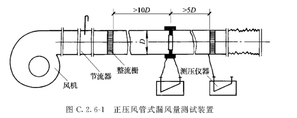
- 风管式漏风量测试装置应由风机、连接风管、测压仪器、整流栅、节流器和标准孔板等组成(图 C.2.6-1)。
C.3 漏风量测试
C.3.1 系统风管与设备的漏风量测试,应分正压试验和负压试验两类。应根据被测风管的工作状态决定,也可采用正压测试来检验。
C.3.2 系统风管漏风量测试可以采用整体或分段进行,测试时被测系统的所有开口均应封闭,不应漏风。
C.3.3 被测系统风管的漏风量超过设计和本规范的规定时,应查出漏风部位(可用听、摸、飘带、水膜或烟检漏),做好标记;修补完工后,应重新测试,直至合格。
C.3.4 漏风量测定一般应为系统规定工作压力(最大运行压力)下的实测数值。特殊条件下,也可用相近或大于规定压力下的测试代替,漏风量可按下式计算:Q0=Q(P0/P)0.65(C.3.4)
式中:
Q0 —— 规定压力下的漏风量 [m3/(h⋅m2)];
Q —— 测试的漏风量 [m3/(h⋅m2)];
P0 —— 风管系统测试的规定工作压力 (Pa);
P —— 测试的压力 (Pa)。
附录 E 通风空调系统运行基本参数测定
E.1 风管风量测量
E.1.1 风管内风量的测量宜采用热风速仪直接测量风管断面平均风速,然后求取风量的方法。
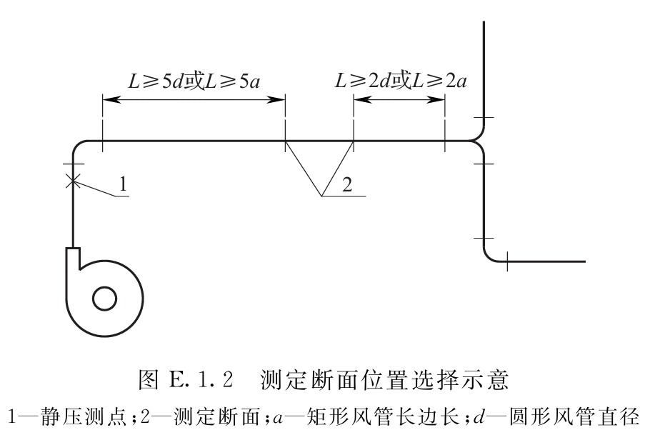
E.1.2 风管风量测量的断面应选择在直管段上,且距上游局部阻力部件不应小于 5 倍管径(或矩形风管长边尺寸),距下游局部阻力构件不应小于 2 倍管径(或矩形风管长边尺寸)的管段位置(图 E.1.2)。
E.1.3 风管风量测量断面测点布置应符合下列规定:
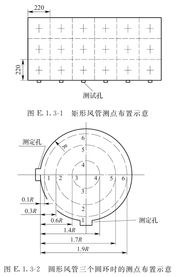
- 矩形风管断面测点数的确定及布置(图 E.1.3-1):应将矩形风管测定断面划分为若干个接近正方形的面积相等的小断面,且面积不应大于 0.05m²,边长不应大于 220mm(虚线分格),测点应位于各个小断面的中心(十字交点)。
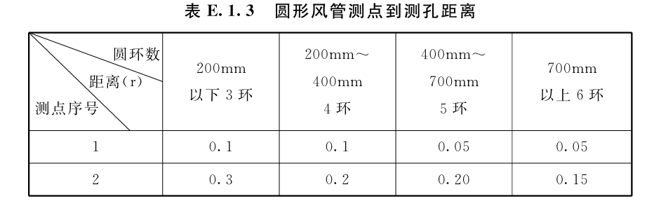
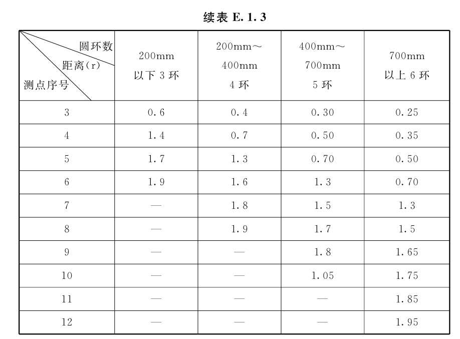
- 圆形风管断面测点数的确定及布置(图 E.1.3-2):应将圆形风管断面划分为若干个面积相等的同心圆环,测点布置在各圆环面积等分线上,并应在相互垂直的两直径上布置两个或四个测孔,各测点到管壁距离应符合表 E.1.3 的规定。
E.1.4 当采用热风速仪测量风速时,风速探头测杆应与风管管壁垂直,风速探头应正对气流吹来方向。
E.1.5 断面平均风速应为各测点风速测量值的平均值,风管实测风量应按下式计算:L=3600×F×V(E.1.5)
式中: F —— 风管测定断面面积(m2);
V —— 风管测定断面平均风速(m/s)。
E.2 风口风量测量
E.2.1 风口风量测量方法选择宜符合下列规定:
- 散流器风口风量,宜采用风量罩法测量。
- 当风口为格栅或网格风口时,宜采用风口风速法测量。
- 当风口为条缝形风口或风口气流有偏移时,宜采用辅助风管法测量。
- 当风口风速法测试有困难时,可采用风管风量法。
E.2.2 风口风量测量应符合下列规定:
- 采用风口风速法测量风口风量时,在风口出口平面上,测点不应少于 6 点,并应均匀布置。
- 采用辅助风管法测量风口风量时,辅助风管的截面尺寸应与风口内截面尺寸相同,长度不应小于 2 倍风口边长。辅助风管应将被测风口完全罩住,出口平面上的测点不应少于 6 点,且应均匀布置。
E.2.3 当采用风量罩测量风口风量时,应选择与风口面积较接近的风量罩罩体,罩口面积不得大于 4 倍风口面积,且罩体长边不得大于风口长边的 2 倍。风口宜位于罩体的中间位置;罩口与风口所在平面应紧密接触、不漏风。
E.2.4 风口风量检测的数据处理应符合下列规定:
- 采用风口风速法(或辅助风管法)测量时,风口风量应按下式计算:
L=3600×F×V(E.2.4)
式中:F—— 风口截面有效面积(或辅助风管的截面积)(); V —— 风口处测得的平均风速()。
- 采用风管风量法测量时,风口风量应按本规范公式 E.1.5 计算。
规范三、《CECS 439-2016 民用建筑新风系统工程技术规程》
1 总 则
1.0.1 为规范我国民用建筑新风系统工程的设计、施工及验收,达到技术先进、经济合理、安全适用、节能环保、保证工程质量,制定本规程。
1.0.2 本规程适用于新建、扩建和改建的民用建筑新风系统的设计、施工及验收。
1.0.3 民用建筑新风系统工程的设计、施工及验收除应执行本规程外,尚应符合国家现行有关标准的规定。
3 设 计
3.1 一般规定
3.1.1 当符合下列条件之一时,宜设置民用建筑新风系统。
1 居住建筑中为满足房间内空气品质要求,但条件限制不能采用自然通风时;
2 公共建筑中有人员长期停留且未设置有组织集中送新风的空调房间。
3.1.2 民用建筑新风系统可分为单向流新风系统、双向流新风系统。
3.1.3 双向流新风系统经技术经济比较合理时,宜设置空气-空气能量回收装置。
3.1.4 设计文件应满足施工图纸标准编制深度要求。
3.2.1 民用建筑新风系统设计新风量应按最小新风量并在结合室内污染物释放总量的基础上确定。
3.2.2 最小新风量的设计应符合下列规定:
1 公共建筑最小新风量应符合表 3.2.1 的规定。
表 3.2.1 公共建筑每人所需最小新风量 [m³/(h·人)]
| 建筑类型 | 房间名称 | 级别/规格 | 新风量 [m³/(h·人)] |
|---|---|---|---|
| 宾馆 | 客房 | 5星级 | 50 |
| 宾馆 | 客房 | 4星级 | 40 |
| 宾馆 | 客房 | 3星级 | 30 |
| 宾馆 | 餐厅、宴会厅、多功能厅 | 5星级 | 30 |
| 宾馆 | 餐厅、宴会厅、多功能厅 | 4星级 | 25 |
| 宾馆 | 餐厅、宴会厅、多功能厅 | 3星级 | 20 |
| 宾馆 | 餐厅、宴会厅、多功能厅 | 2星级 | 15 |
| 宾馆 | 大堂、四季厅 | 4~5星级 | 10 |
| 宾馆 | 商业、服务 | 4~5星级 | 20 |
| 宾馆 | 商业、服务 | 2~3星级 | 10 |
| 宾馆 | 美容、理发、康乐设施 | 30 | |
| 旅店 | 客房 | 一~三级 | 30 |
| 旅店 | 客房 | 四级 | 20 |
| 旅店 | 游艺厅、舞厅(包括卡拉OK歌厅) | 30 | |
| 旅店 | 酒吧、茶座、咖啡厅 | 10 | |
| 商场建筑 | 商场(店)、书店 | 20 | |
| 商场建筑 | 饭馆(餐厅) | 20 | |
| 学校 | 教室 | 小学 | 11 |
| 学校 | 教室 | 初中 | 14 |
| 学校 | 教室 | 高中 | 17 |
| 医院 | 候诊室 | 30 | |
| 医院 | 病房 | 大 | 50 |
| 医院 | 病房 | 小 | 35 |
| 医院 | 诊室 | 25 | |
| 办公建筑 | 办公室(无烟) | 高级 | 35 |
| 办公建筑 | 办公室(无烟) | 一般 | 25 |
| 办公建筑 | 会议室 | 30 | |
| 文体建筑 | 影剧院、音乐厅 | 观众厅 | 20 |
| 文体建筑 | 体育馆 | 观众厅 | 20 |
| 文体建筑 | 室内游泳池 | 10 | |
| 文体建筑 | 展览馆、博物馆 | 展厅、观众厅 | 10 |
| 文体建筑 | 图书馆 | 阅览室 | 15 |
2 居住建筑最小新风量宜按换气次数确定,每小时换气次数宜符合表 3.2.2 的规定。
表 3.2.2 居住建筑每小时换气次数
| 人均居住面积 (F_p) | 每小时换气次数 |
|---|---|
| (F_p \le 10m^2) | 0.70 |
| (10m^2 < F_p \le 20m^2) | 0.60 |
| (20m^2 < F_p \le 50m^2) | 0.50 |
| (F_p > 50m^2) | 0.45 |
3.3 新风处理
3.3.1 对进入室内的室外空气应根据室外空气参数和室内使用功能进行净化、加热、冷却、加湿、除湿等处理。
3.3.2 新风的加热、冷却宜选用建筑物已有的冷、热源。
3.3.3 选配的加湿装置性能应符合现行国家标准《空调设备用加湿器》GB/T 29736 的有关规定。
3.3.4 选配的空气过滤器性能应符合现行国家标准《空气过滤器》GB/T 14295 的有关规定,过滤器宜设置过滤器更换报警装置。
3.3.5 选配的除湿装置应满足设计要求。
3.3.6 新风净化装置的使用,不应产生新的污染源。
3.4 新风主机选型
3.4.1 新风主机的功能和类型应根据建筑物的使用要求、地域条件、大气污染水平、节能标准、现场的安装条件等因素确定。
3.4.2 新风主机的风量宜按漏风、混风等因素附加 5%~10%。
3.4.3 新风主机台数的确定应考虑使用功能、主机的尺寸、安装位置的空间尺寸、检修空间、噪声控制等因素。
3.4.4 符合下列情况之一的区域,宜分别设置新风主机。
1 使用功能不同;
2 使用时间、频次不同;
3 温湿度基数和允许波动范围不同;
4 空气洁净度标准要求不同;
5 噪声要求标准不同;
6 面积较大的公寓、别墅应分成若干区域,每个区域设置一台主机,单台主机不宜跨楼层使用。
3.4.5 新风主机风压应符合设计要求。
3.4.6 新风主机应采取保温措施,防止能量损失或结露。
3.4.7 空气-空气能量回收装置的选用及系统的设计应符合下列规定:
1 能量回收装置在规定工况下的交换效率,应符合现行国家标准《空气-空气能量回收装置》GB/T 21087 的有关规定。
2 采用空气-空气热回收装置时,应对热回收装置的排风侧有无结霜或结露现象进行核算。当出现结霜或结露时,应采取预热等保温防冻及冷凝水收集排放措施,并应符合本规程附录 A 的规定。
3 冬季需除湿的新风系统,应采用显热回收装置。
4 夏热冬暖地区空气湿度大,应选用全热回收装置;严寒地区气候干燥,宜选用显热回收装置;其他地区宜选用全热回收装置。
5 排风进入空气能量回收装置前应设置过滤器。
3.5 风管设计
3.5.1 风管的设计应符合现行国家标准《民用建筑供暖通风与空气调节设计规范》GB 50736 的有关规定。
3.5.2 风管材料选择应符合现行国家标准《建筑设计防火规范》GB 50016 的有关规定。
3.5.3 新风系统风管的设计应符合下列规定:
1 风管宜采用圆形、扁圆形或矩形,矩形风管长短边比不宜大于 4,且不应超过 10。
2 风管改变方向、变径及分路时,不宜使用矩形箱式管件代替弯管、变径管、三通等管件;必须使用分配气流的静压箱时,其断面风速不宜大于 1.5m/s。
3 风管的变径管应做成渐扩或渐缩形,其每边扩大收缩角度不宜大于 30°。
4 弯头、三通、调节阀、变径管等管件之间管段长度,不宜小于 5 倍~10 倍当量管径。
5 风管内的空气流速应符合表 3.5.3-1 的规定。当有消声要求时,风管内的空气流速应符合表 3.5.3-2 的规定。
6 主机的进风或出风口处应设置与主机自动连锁启闭的电动密闭风阀。
7 风管内设有电加热装置时,电加热装置前后各 800mm 范围内的风管、穿过设有火源等容易起火房间的风管及其保温材料均应采用难燃材料,并应符合相关电气安全及消防标准的规定。
8 当风管内可能产生结露时,风管应设置大于或等于 5‰ 的坡度,并在风管的最低点和主机的底部设排水装置。
9 风管应根据实际情况进行保温处理。
10 选择有加湿装置时,风管应考虑材料的耐腐蚀性。
表 3.5.3-1 风管内的空气流速 (m/s) (续)
| 风管分类 | 居住建筑(推荐值) | 居住建筑(最大) | 公共建筑(推荐值) | 公共建筑(最大) |
|---|---|---|---|---|
| 从支管上接出的风管 | 2.5 | 4.0 | 3.0~3.5 | 6.0 |
| 主机入口 | 3.5 | 4.5 | 4.0 | 5.0 |
| 主机出口 | 5.0~8.0 | 8.5 | 6.5~10.0 | 11.0 |
表 3.5.3-2 有消声要求风管内的空气流速 (m/s)
| 室内允许噪声等级 dB(A) | 干管风速 | 支管风速 |
|---|---|---|
| 25~35 | 3~4 | ≤2 |
| 35~50 | 4~7 | 2~3 |
3.6 气流组织
3.6.1 气流组织设计,应根据建筑物的用途对送风区域内温湿度参数、允许风速、噪声标准、空气质量及空气分布特性指标的要求,结合建筑物特点、内部装修或家具布置等进行设计、计算。
3.6.2 送、排风方式可分为上送上排、上送下排、下送上排、侧送上排、侧送同侧排、侧送对侧排六种形式。
3.6.3 室内新风口的风速,应根据送风方式、送风口类型、安装高度、室内允许风速和噪声标准等确定。当消声要求较高时,室内新风口的风速宜采用 2m/s~3m/s。室内新风口应设置调节风量装置。
3.6.4 室内排风口不应设在送风射流区内和人员经常停留的地方,室内排风口的空气流速宜按表 3.6.4 选用。
表 3.6.4 室内排风口的空气流速 (m/s)
| 室内排风口所在位置 | 空气流速 | |
|---|---|---|
| 房间内的上部 | 4.0~5.0 | |
| 房间内的下部 | 不靠近座位 | 3.0~4.0 |
| 房间内的下部 | 靠近座位 | 1.5~2.0 |
| 通过隔墙设置排风口的无组织排风 | 1.0~1.5 |
4 施 工
4.1 一般规定
4.1.1 施工前应具备下列条件:
1 设计文件齐备,且已审查通过。
2 施工组织设计及施工方案已经批准。
3 施工场地符合施工组织设计和安全生产要求。
4 现场条件满足正常施工需要。
5 预留基础、孔洞、设施符合设计图纸要求。
4.1.2 新风系统宜按下列流程进行施工:
图纸会审 -> 施工准备 -> 材料设备进场 -> 安装新风主机 -> 风管制作及安装 -> 风阀、风口安装 -> 电气系统安装。
4.2 施 工
4.2.1 主机宜设置在机房内或安装在对噪音要求不高的场所的吊顶内,并应方便维护和维修。
4.2.2 主机应固定牢固,宜设置抗震支吊架。
4.2.3 民用建筑新风系统的风管系统属于低压风管系统,系统的安装应符合现行国家标准《通风与空调工程施工质量验收规范》GB 50243 的有关规定。
4.2.4 民用建筑新风系统严密性检测应采用漏光法检测合格,并应符合本规程附录 B 的规定。
4.2.5 室外风口、风帽的安装应做好防水和密封处理。
4.2.6 电源线应根据主机附带的安全说明、输入功率、电压等参数进行配置。
4.2.7 电源应独立供给,接线应正确、坚固,并有良好接地;电源线应绝缘良好,不得裸露在外面;新风主机应有独立的控制回路及开关装置。
4.2.8 管道施工过程中和施工完毕后应保持管道系统的封闭,避免杂物和灰尘进入。
4.2.9 带加湿功能的新风系统,水系统应配置手动检修阀门。
4.2.10 产生冷凝水或排水部位应设置排水口及水封装置。冷凝水管道应采取保湿措施。
5 调试与验收
5.1 系统调试
5.1.1 系统调试所使用的测试仪器和仪表性能应稳定可靠,其精度等级及最小分度值应能满足测定要求,并应符合国家计量法规及检定规程的规定。
5.1.2 系统安装完毕,应进行系统调试和试运转,且连续试运转时间不应小于 2h。
5.1.3 系统试运转及调试应符合下列规定:
1 主机中的风机、叶轮旋转方向正确,运转平稳,无异常振动与声响,电机运行功率应符合主机设备技术文件规定。
2 主机运行时,产生的噪声不宜超过产品性能说明书的规定值。
3 主机总风量调试结果与设计风量的偏差不应大于 10%。
4 新风系统经平衡调整,各风口的风量与设计风量的允许偏差不应大于 15%。
5 房间内噪声应满足设计要求。
6 系统工程的控制与检测设备,应能与系统的检测原件和执行机构正常沟通,系统的状态参数应能正确显示,设备连锁、自动调节、自动保护应能正确动作。
5.2 竣工验收
5.2.1 系统工程的竣工验收,应由建设单位负责,组织施工、设计、监理等单位共同进行,并按本规程附录 C 填写相关记录。合格后应办理竣工验收手续。
5.2.2 系统工程的竣工验收时,应检查竣工验收的资料,宜包括下列文件及记录:
1 图纸会审记录、设计变更通知书和竣工图。
2 主要材料、设备、成品、半成品和仪表的出厂合格证明及进场检(试)验报告。
3 隐蔽工程检查验收记录。
4 风管系统安装及检验记录。
5 新风系统试运转与调试记录。
6 感官质量综合检查记录。
5.2.3 系统自竣工验收合格日起保修期 2 年,在保修期内发生施工质量问题的,施工企业应履行保修职责,责任方承担相应的经济责任。
附录B 漏光法检测
B.0.1 漏光法检测是利用光线对小孔的强穿透力,对系统风管严密程度进行检测的方法。
B.0.2 检测应采用具有一定强度的安全光源。手持移动光源可采用不低于 100W 带保护罩的低压照明灯,或其他低压光源。
B.0.3 系统风管采用漏光法检测时,光源可置于风管内侧或外侧,但其相对侧应为暗黑环境。检测光源应沿着被检测接口部位与接缝做缓慢移动,在另一旁进行观察,当发现有光线射出,则说明查到明显漏风处,并应做好记录。
B.0.4 对系统风管的检测,宜采用分段检测、汇总分析的方法。在严格安装质量管理的基础上,系统风管的检测以长管和干管为主。当采用漏光法检测系统的严密性时,低压系统风管以每 10m 接缝,漏光点不大于 2 处,且 100m 接缝平均不大于 16 处为合格;中压系统风管每 10m 接缝,漏光点不大于 1 处,且 100m 接缝平均不大于 8 处为合格。
B.0.5 漏光法检测中对发现的条缝形漏光,应做密封处理。
本规程用词说明
1 为便于在执行本规程条文时区别对待,对要求严格程度不同的用词说明如下:
1) 表示很严格,非这样做不可的:正面词采用“必须”,反面词采用“严禁”;
2) 表示严格,在正常情况下均应这样做的:正面词采用“应”,反面词采用“不应”或“不得”;
3) 表示允许稍有选择,在条件许可时首先应这样做的:正面词采用“宜”,反面词采用“不宜”;
4) 表示有选择,在一定条件下可以这样做的,采用“可”。
2 条文中指明应按其他有关标准执行的写法为:“应符合……的规定”或“应按……执行”。
规范四、WS 394-2012.公共场所集中空调通风系统卫生规范(2020年复审继续有效)
公共场所集中空调通风系统卫生规范
1 范围
本标准规定了公共场所集中空调通风系统(以下简称集中空调系统)的设计、质量、检验和管理等卫生要求。
本标准适用于公共场所使用的集中空调系统,其他场所集中空调系统可参照执行。
2 术语和定义
下列术语和定义适用于本文件。
2.1 新风量 air change flow
单位时间内由集中空调系统进入室内的室外空气的量,单位为 m³/(h·人)。
2.2 可吸入颗粒物 inhalable particle matter
悬浮在空气中,空气动力学当量直径小于等于 10 μm,能够进入人体喉部以下呼吸道的颗粒状物质,简称 PM10。
2.3 风管表面积尘量 duct surface dust
集中空调风管内表面单位面积灰尘的量,单位为 g/m²。
3 设计卫生要求
3.1 集中空调系统新风量的设计应符合表 1 的要求。
表 1 新风量要求
| 场所名称 | 新风量 [m³/(h·人)] |
|---|---|
| 宾馆、饭店、旅店、招待所、候诊室、理发店、美容店、游泳场(馆)、博物馆、美术馆、图书馆、游艺厅(室)、舞厅等 | ≥30 |
| 饭馆、咖啡馆、酒吧、茶座、影剧院、录像厅(室)、音乐厅、公共浴室、体育场(馆)、展览馆、商场(店)、书店、候车(机、船)室、公共交通工具等 | ≥20 |
3.2 集中空调系统送风温度的设计宜使公共浴室的更衣室、休息室冬季室内温度达到 25 ℃,其他公共场所应在 16 ℃~20 ℃之间;夏季室内温度在 26 ℃~28 ℃之间。
3.3 集中空调系统送风湿度的设计宜使游泳场(馆)相对湿度不大于 80%,其他公共场所相对湿度在 40%~65%之间。
3.4 集中空调系统送风风速的设计宜使宾馆、旅店、招待所、咖啡馆、酒吧、茶座、理发店、美容店及公共浴室的更衣室、休息室风速不大于 0.3 m/s。其他公共场所风速不大于 0.5 m/s。
3.5 对有睡眠、休憩需求的公共场所,集中空调系统运行所产生的噪声对场所室内环境造成的影响不得高于设备设施关闭状态时室内环境噪声值 5 dB(A 计权)。
3.6 集中空调系统应具备下列设施:
a) 应急关闭回风和新的装置;
b) 控制空调系统分区域运行的装置;
c) 供风管系统清洗、消毒用的可开闭窗口,或便于拆卸的不小于 300 mm × 250 mm 的风口。
3.7 集中空调系统宜设置去除送风中微生物、颗粒物和气态污染物的空气净化消毒装置。
3.8 集中空调系统的新风应直接取自室外,不应从机房、楼道及天棚吊顶等处间接吸取新风。
3.9 集中空调系统的新风口应设置防护网和初效过滤器,并符合以下要求:
a) 设置在室外空气清洁的地点,远离开放式冷却塔和其他污染源;
b) 低于排风口;
c) 进风口的下缘距室外地坪不宜小于 2 m,当设在绿化地带时,不宜小于 1 m;
d) 进排风不应短路。
3.10 集中空调系统的送风口和回风口应设置防虫媒装置,设备冷凝水管道应设置水封。
3.11 集中空调系统加湿方式宜选用蒸汽加湿,选用自来水喷雾或冷水蒸发的加湿方式应有控制军团菌繁殖措施。
3.12 集中空调系统开放式冷却塔应符合下列要求:
a) 开放式冷却塔的设置应远离人员聚集区域、建筑物新风取风口或自然通风口,不应设置在新风口的上风向,宜设置冷却水系统持续消毒装置;
b) 开放式冷却塔应设置有效的除雾器和加注消毒剂的入口;
c) 开放式冷却塔水池内侧应平滑,排水口应设在塔池的底部。
3.13 集中空调系统风管内表面应当光滑,易于清理。制作风管的材料不得释放有毒有害物质,宜使用耐腐蚀的金属材料;采用非金属材料制作风管时,必须保证风管的坚固及严密性,具有承受机械清洗设备工作冲击的强度。
4 卫生质量要求
4.1 集中空调系统新风量应符合表1的要求。
4.2 集中空调系统冷却水和冷凝水中不得检出嗜肺军团菌。
4.3 集中空调系统送风质量应符合表2的要求。
表 2 送风卫生指标
| 项目 | 指标 |
|---|---|
| PM₁₀ | ≤0.15 mg/m³ |
| 细菌总数 | ≤500 CFU/m³ |
| 真菌总数 | ≤500 CFU/m³ |
| β-溶血性链球菌 | 不得检出 |
| 嗜肺军团菌 (不作为许可的必检项目) | 不得检出 |
4.4 集中空调系统风管内表面卫生指标应符合表3的要求。
表 3 风管内表面卫生指标
| 项目 | 指标 |
|---|---|
| 积尘量 | ≤20 g/m² |
| 细菌总数 | ≤100 CFU/cm² |
| 真菌总数 | ≤100 CFU/cm² |
5 卫生管理要求
5.1 应建立集中空调系统卫生档案,主要包括以下内容:
a) 集中空调系统竣工图;
b) 卫生学检测或评价报告书;
c) 经常性卫生检查及维护记录;
d) 清洗、消毒及其资料记录;
e) 空调故障、事故及其他特殊情况记录。
5.2 应定期对集中空调系统进行检查、检测和维护。
5.3 应定期对集中空调系统下列部位进行清洗:
a) 开放式冷却塔每年清洗不少于一次;
b) 空气净化过滤材料应当每六个月清洗或更换一次;
c) 空气处理机组、表冷器、加热(湿)器、冷凝水盘等每年清洗一次。
5.4 集中空调系统出现下列情况时,应对相关部位进行清洗消毒:
a) 冷却水、冷凝水中检出嗜肺军团菌;
b) 送风质量不符合表2要求的;
c) 风管内表面积尘量、细菌总数、真菌总数有不符合表3要求的。
5.5 应制定集中空调系统预防空气传播性疾病的应急预案,主要包括以下内容:
a) 集中空调系统进行应急处理的责任人;
b) 不同送风区域隔离控制措施、最大新风量或全新风运行方案、空调系统的清洗、消毒方法等;
c) 集中空调系统停用后应采取的其他通风与调温措施等。
5.6 当空气传播性疾病暴发流行时,符合下列条件之一的集中空调系统方可继续运行:
a) 采用全新风方式运行的;
b) 装有空气净化消毒装置,并保证该装置有效运行的;
c) 风机盘管加新风的空调系统,能确保各房间独立通风的。
5.7 当空气传播性疾病暴发流行时,应每周对运行的集中空调系统的开放式冷却塔、过滤网、过滤器、净化器、风口、空气处理机组、表冷器、加热(湿)器、冷凝水盘等设备或部件进行清洗、消毒或者更换。
6 卫生检测要求
6.1 检测样本量
6.1.1 抽样比例不应少于空气处理机组对应的风管系统总数量的5%;不同类型的集中空调系统,每类至少抽1套。
6.1.2 每套应选择 2 个~5 个代表性部位。
6.1.3 集中空调系统的冷却水和冷凝水分别不应少于 1 个部位。
6.2 检验方法
6.2.1 集中空调系统新风量检测方法见附录 A。
6.2.2 集中空调系统冷却水、冷凝水中嗜肺军团菌检验方法见附录 B。
6.2.3 集中空调送风中可吸入颗粒物检测方法见附录 C。
6.2.4 集中空调送风中细菌总数检验方法见附录 D。
6.2.5 集中空调送风中真菌总数检验方法见附录 E。
6.2.6 集中空调送风中 β-溶血性链球菌检验方法见附录 F。
6.2.7 集中空调送风中嗜肺军团菌检验方法见附录 G。
6.2.8 集中空调风管内表面积尘量检验方法见附录 H。
6.2.9 集中空调风管内表面微生物检验方法见附录 I。
6.3 检验结果判定
当检测结果为下列情况之一的,判定该套集中空调系统不符合卫生质量要求:
a) 冷却水或冷凝水中有嗜肺军团菌检出的;
b) 新风量检测结果不符合表 1 要求的;
c) 单个风口送风中细菌总数、真菌总数、β-溶血性链球菌、嗜肺军团菌检测结果有不符合表 2 要求的;
d) 抽取的各个风口送风中 PM₁₀ 的平均值不符合表 2 要求的;
e) 风管内表面积尘中细菌总数、真菌总数检测结果有不符合表 3 要求的;
f) 风管内表面各采样点积尘量检测结果的平均值不符合表 3 要求的。
附录 A
(规范性附录)
集中空调系统新风量检测方法
A.1 总则
本附录规定了用风管法测定集中空调系统的新风量,即直接在新风管上测定新风量的方法。
A.2 原理
在机械通风系统处于正常运行或规定的工况条件下,通过测量新风管某一断面的面积及该断面的平均风速,计算出该断面的新风量。如果一套系统有多个新风管,每个新风管均要测定风量,全部新风管风量之和即为该套系统的总新风量,根据系统服务区域内的人数,便可得出新风量结果。
A.3 仪器
A.3.1 标准皮托管:(K_p = 0.99 \pm 0.01),或 S 型皮托管 (K_p = 0.84 \pm 0.01)。
A.3.2 微压计:精确度不低于 2%,最小读数不大于 1 Pa。
A.3.3 热电风速仪:最小读数不大于 0.1 m/s。
A.3.4 玻璃液体温度计或电阻温度计:最小读数不大于 1 ℃。
A.4 测点要求
A.4.1 检测点所在的断面应选在气流平稳的直管段,避开弯头和断面急剧变化的部位。
A.4.2 圆形风管测点位置和数量:将风管分成适当数量的等面积同心环,测点选在各环面积中心线与垂直的两条直径线的交点上,圆形风管测点数见表 A.1。直径小于 0.3 m、流速分布比较均匀的风管,可取风管中心一点作为测点。气流分布对称和比较均匀的风管,可只取一个方向的测点进行检测。
表 A.1 圆形风管测点数
| 风管直径 (m) | 环数 (个) | 测点数 (两个方向共计) |
|---|---|---|
| ≤1 | 1~2 | 4~8 |
| >1~2 | 2~3 | 8~12 |
| >2~3 | 3~4 | 12~16 |
A.4.3 矩形风管测点位置和数量:将风管断面分成适当数量的等面积矩形(最好为正方形),各矩形中心即为测点。矩形风管测点数见表 A.2。
表 A.2 矩形风管测点数
| 风管断面面积 (m²) | 等面积矩形数 (个) | 测点数 (个) |
|---|---|---|
| ≤1 | 2×2 | 4 |
| >1~4 | 3×3 | 9 |
| >4~9 | 3×4 | 12 |
| >9~16 | 4×4 | 16 |
A.5 测量步骤
A.5.1 测量风管检测断面面积((F)),按表 A.1 或表 A.2 分环(分块)确定检测点。
A.5.2 皮托管法测定新风量测量步骤如下:
a) 检查微压计显示是否正常,微压计与皮托管连接是否漏气;
b) 将皮托管全压出口与微压计正压端连接,静压管出口与微压计负压端连接;
c) 将皮托管插入风管内,在各测点上使皮托管的全压测孔对着气流方向,偏差不得超过 10°,测量出各点动压((P_d))。重复测量一次,取算术平均值;
d) 将玻璃液体温度计或电阻温度计插入风管中心点处,封闭测孔待温度稳定后读数,测量出新风温度((t));
e) 调查机械通风服务区域内设计人流量和实际最大人流量。
A.5.3 风速计法测定新风量测量步骤如下:
a) 按照热电风速仪使用说明书调整仪器;
b) 将风速仪放入新风管内测量各测点风速,以全部测点风速算术平均值作为平均风速;
c) 将玻璃液体温度计或电阻温度计插入风管中心点处,封闭测孔待温度稳定后读数,测量出新风温度((t));
d) 调查机械通风服务区域内设计人流量和实际最大人流量。
A.5.4 按要求对仪器进行期间核查和使用前校准。
A.6 结果计算
A.6.1 皮托管法测量新风量的计算见式(A.1):
$$
Q = \frac{\sum_{i=1}^{n} (3600 \times F \times 0.076 \times K_p \times \sqrt{273+t} \times \sqrt{P_d})}{P} \quad \cdots\cdots\cdots\cdots\cdots\cdots\cdots\cdots\cdots\cdots (A.1)
$$
式中:
(Q) ——新风量,单位为立方米每人每小时[m³/(h·人)];
(F) ——新风管测量断面面积,单位为平方米(m²);
(K_p) ——皮托管系数;
(t) ——新风温度,单位为摄氏度(℃);
(P_d) ——新风动压值,单位为帕(Pa);
(n) ——一个机械通风系统内新风管的数量;
(P) ——服务区人数,取设计人流量与实际最大人流量 2 个数中的高值,单位为人。
A.6.2 风速计法测量新风量的计算见式(A.2):
$$
Q = \frac{\sum_{i=1}^{n} (3600 \times F \times \bar{V})}{P} \quad \cdots\cdots\cdots\cdots\cdots\cdots\cdots\cdots\cdots\cdots (A.2)
$$
式中:
(Q) ——新风量,单位为立方米每人每小时[m³/(h·人)];
(F) ——新风管测量断面面积,单位为平方米(m²);
(\bar{V}) ——新风管中空气的平均速度,单位为米每秒(m/s);
(n) ——一个系统内新风管的数量;
(P) ——服务区人数,取设计人流量与实际最大人流量 2 个数中的高值,单位为人。
A.6.3 换气次数的计算见式(A.3):
$$
A = \frac{Q \times P}{V} \quad \cdots\cdots\cdots\cdots\cdots\cdots\cdots\cdots\cdots\cdots (A.3)
$$
式中:
(A) ——换气次数,单位为次每小时(次/h);
(Q) ——新风量,单位为立方米每人每小时[m³/(h·人)];
(P) ——服务区人数;
(V) ——室内空气体积,单位为立方米(m³)。
A.7 测量范围
皮托管法测量新风管风速范围为 2 m/s~30 m/s,电风速计法测量新风管风速范围为 0.1 m/s~10 m/s。
规范五、ASHRAE+62.1-2022
6. PROCEDURES
6.1 General. The Ventilation Rate Procedure (VRP), the Indoor Air Quality Procedure (IAQP), the Natural Ventilation Procedure, or a combination thereof shall be used to meet the requirements of this section. In addition, the requirements for exhaust ventilation in Section 6.5 shall be met regardless of the method used to determine minimum outdoor airflow rates.
Informative Note: Although the intake airflow determined using each of these approaches may differ significantly because of assumptions about the design, any of these approaches is a valid basis for design.
6.1.1 Ventilation Rate Procedure. The prescriptive design procedure presented in Section 6.2, in which outdoor air intake rates are determined based on space type/application, occupancy level, and floor area, shall be permitted to be used for any zone or system.
6.1.2 Indoor Air Quality Procedure. The IAQP is an alternative to the VRP used to determine the design rate of outdoor airflow to maintain concentrations of design compounds (DCs) and PM2.5 in the indoor environment to be less than design limits (DLs), based on indoor and outdoor sources, air cleaning, and other variables. These outdoor air requirements shall be calculated with mass-balance equations. Verification of occupant satisfaction and indoor DC concentrations shall be performed after the building is completed.
6.1.3 Natural Ventilation Procedure. The prescriptive or engineered system design procedure presented in Section 6.4, in which outdoor air is provided through openings to the outdoors, shall be permitted to be used for any zone or portion of a zone in conjunction with mechanical ventilation systems in accordance with Section 6.4.
6.1.4 Outdoor Air Treatment. Each ventilation system that provides outdoor air shall comply with Sections 6.1.4.1 through 6.1.4.4.
Exception to 6.1.4: Systems supplying air for enclosed parking garages, warehouses, storage rooms, janitor’s closets, trash rooms, recycling areas, shipping/receiving/distribution areas.
Informative Note: Occupied spaces ventilated with outdoor air that is judged to be unacceptable are subject to reduced air quality when outdoor air is not cleaned prior to introduction to the occupied spaces.
6.1.4.1 Particulate Matter Smaller than 10 Micrometers (PM10). In buildings located in an area where the national standard or guideline for PM10 is exceeded, particle filters or air-cleaning devices shall be provided to clean the outdoor air at any location prior to its introduction to occupied spaces. Particulate matter filters or air cleaners shall have either
a. a MERV of not less than 8 where rated in accordance with ASHRAE Standard 52.2 or
b. the minimum efficiency within ISO ePM10 where rated in accordance with ISO 16890.
Informative Note: See Informative Appendix E for resources regarding selected PM10 national standards and guidelines.
6.1.4.2 Particulate Matter Smaller than 2.5 Micrometers (PM2.5). In buildings located in an area where the national standard or guideline for PM2.5 is exceeded, particle filters or air-cleaning devices shall be provided to clean the outdoor air at any location prior to its introduction to occupied spaces. Particulate matter filters or air cleaners shall have either
a. a MERV of not less than 11 where rated in accordance with ASHRAE Standard 52.2 or
b. the minimum efficiency within ISO ePM2.5 where rated in accordance with ISO 16890.
Informative Note: See Informative Appendix E for resources regarding selected PM2.5 national standards and guidelines.
6.1.4.3 Ozone. Air-cleaning devices for ozone shall be provided when the most recent three-year average annual fourth-highest daily maximum eight-hour average ozone concentration exceeds 0.100 ppm (195 µg/m³).
Such air-cleaning devices shall have a volumetric ozone removal efficiency of not less than 40% where installed, operated, and maintained in accordance with the manufacturer’s recommendations and shall be approved by the AHJ. Such devices shall be operated where the outdoor ozone levels are expected to exceed 0.100 ppm (195 µg/m³).
Exceptions to 6.1.4.3: Air cleaning for ozone shall not be required where
- the system design outdoor air intake flow is 1.5 ach or less,
- controls are provided that sense outdoor ozone level and reduce intake airflow to 1.5 ach or less while complying with the outdoor airflow requirements of Section 6, or
- outdoor air is brought into the building and heated by direct-fired makeup air units.
Informative Note: In the U.S., a most recent three-year average annual fourth-highest daily maximum eight-hour average ozone concentration exceeding 0.100 ppm (195 µg/m³) equates to a U.S. EPA eight-hour ozone classification of “Serious” or higher (Severe 15, Severe 17, or Extreme).
6.1.4.4 Other Outdoor Contaminants. In buildings located in an area where the national standard for one or more contaminants not addressed in Section 6.1.4 is exceeded, any design assumptions and calculations related to the impact on IAQ shall be included in the design documents.
6.2 Ventilation Rate Procedure. The outdoor air intake flow ((V_{ot})) for a ventilation system shall be determined in accordance with Section 6.1.4 and Sections 6.2.1 through 6.2.6.
Informative Note: Additional explanation of terms used below is contained in Normative Appendix A, along with a ventilation system schematic (Figure A-1).
6.2.1 Zone Calculations. Ventilation zone parameters shall be determined in accordance with Sections 6.2.1.1 through Section 6.2.1.3 for ventilation zones served by the ventilation system, except that the ventilation rates from ASHRAE/ASHE Standard 170 shall be used for the occupancy categories within the scope of ASHRAE/ASHE Standard 170. For outpatient facilities outside the scope of ASHRAE/ASHE Standard 170, refer to Normative Appendix D.
Informative Note: The ventilation rates in ASHRAE/ASHE Standard 170 are intended to achieve asepsis and control odor migration and might not be adequate to achieve acceptable IAQ as defined in Standard 62.1.
6.2.1.1 Breathing Zone Outdoor Airflow. The outdoor airflow required in the breathing zone ((V_{bz})) of the occupiable space or spaces in a ventilation zone shall not be less than the value determined in accordance with Equation 6-1.
$$
V_{bz} = R_p \times P_z + R_a \times A_z \tag{6-1}
$$
where
(A_z) = zone floor area, the net occupiable floor area of the ventilation zone, ft² (m²)
(P_z) = zone population, the number of people in the ventilation zone during use
Table 6-1 Minimum Ventilation Rates in Breathing Zone
| Occupancy Category | People Outdoor Air Rate (R_p) (cfm/person) | People Outdoor Air Rate (R_p) (L/s·person) | Area Outdoor Air Rate (R_a) (cfm/ft²) | Area Outdoor Air Rate (R_a) (L/s·m²) | Default Values Occupant Density (#/1000 ft² or #/100 m²) | Air Class | OS (6.2.6.1.4) |
|---|---|---|---|---|---|---|---|
| Animal Facilities | |||||||
| Animal exam room (veterinary office) | 10 | 5 | 0.12 | 0.6 | 20 | 2 | |
| Animal imaging (MRI/CT/PET) | 10 | 5 | 0.18 | 0.9 | 20 | 3 | |
| Animal operating rooms | 10 | 5 | 0.18 | 0.9 | 20 | 3 | |
| Animal postoperative recovery room | 10 | 5 | 0.18 | 0.9 | 20 | 3 | |
| Animal preparation rooms | 10 | 5 | 0.18 | 0.9 | 20 | 3 | |
| Animal procedure room | 10 | 5 | 0.18 | 0.9 | 20 | 3 | |
| Animal surgery scrub | 10 | 5 | 0.18 | 0.9 | 20 | 3 | |
| Large-animal holding room | 10 | 5 | 0.18 | 0.9 | 20 | 3 | |
| Necropsy | 10 | 5 | 0.18 | 0.9 | 20 | 3 | |
| Small-animal-cage room (static cages) | 10 | 5 | 0.18 | 0.9 | 20 | 3 | |
| Small-animal-cage room (ventilated cages) | 10 | 5 | 0.18 | 0.9 | 20 | 3 | |
| Correctional Facilities | |||||||
| Booking/waiting | 7.5 | 3.8 | 0.06 | 0.3 | 50 | 2 | |
| Cell | 5 | 2.5 | 0.12 | 0.6 | 25 | 2 | |
| Dayroom | 5 | 2.5 | 0.06 | 0.3 | 30 | 1 | |
| Guard stations | 5 | 2.5 | 0.06 | 0.3 | 15 | 1 | |
| Educational Facilities | |||||||
| Art classroom | 10 | 5 | 0.18 | 0.9 | 20 | 2 | |
| Classrooms (ages 5 to 8) | 10 | 5 | 0.12 | 0.6 | 25 | 1 | |
| Classrooms (age 9 plus) | 10 | 5 | 0.12 | 0.6 | 35 | 1 | |
| Computer lab | 10 | 5 | 0.12 | 0.6 | 25 | 1 | |
| Daycare sickroom | 10 | 5 | 0.18 | 0.9 | 25 | 3 | |
| Daycare (through age 4) | 10 | 5 | 0.18 | 0.9 | 25 | 2 | |
| Lecture classroom | 7.5 | 3.8 | 0.06 | 0.3 | 65 | 1 | ✓ |
| Lecture hall (fixed seats) | 7.5 | 3.8 | 0.06 | 0.3 | 150 | 1 | ✓ |
| Libraries | 5 | 2.5 | 0.12 | 0.6 | 10 | 1 | |
| Media center | 10 | 5 | 0.12 | 0.6 | 25 | 1 | |
| Multiuser assembly | 7.5 | 3.8 | 0.06 | 0.3 | 100 | 1 | ✓ |
| Music/theater/dance | 10 | 5 | 0.06 | 0.3 | 35 | 1 | ✓ |
| Science laboratories | 10 | 5 | 0.18 | 0.9 | 25 | 2 | |
| University/college laboratories | 10 | 5 | 0.18 | 0.9 | 25 | 2 | |
| Wood/metal shop | 10 | 5 | 0.18 | 0.9 | 20 | 2 | |
| Food and Beverage Service | |||||||
| Bars, cocktail lounges | 7.5 | 3.8 | 0.18 | 0.9 | 100 | 2 | |
| Cafeteria/fast-food dining | 7.5 | 3.8 | 0.18 | 0.9 | 100 | 2 | |
| Kitchen (cooking) | 7.5 | 3.8 | 0.12 | 0.6 | 20 | 2 | |
| Restaurant dining rooms | 7.5 | 3.8 | 0.18 | 0.9 | 70 | 2 | |
| General | |||||||
| Break rooms | 5 | 2.5 | 0.06 | 0.3 | 25 | 1 | ✓ |
| Coffee stations | 5 | 2.5 | 0.06 | 0.3 | 20 | 1 | ✓ |
| Conference/meeting | 5 | 2.5 | 0.06 | 0.3 | 50 | 1 | ✓ |
| Corridors | — | — | 0.06 | 0.3 | — | 1 | ✓ |
| Occupiable storage rooms for liquids or gels | 5 | 2.5 | 0.12 | 0.6 | 2 | 2 | |
| Hotels, Motels, Resorts, Dormitories | |||||||
| Barracks sleeping areas | 5 | 2.5 | 0.06 | 0.3 | 20 | 1 | ✓ |
| Bedroom/living room | 5 | 2.5 | 0.06 | 0.3 | 10 | 1 | ✓ |
| Laundry rooms, central | 5 | 2.5 | 0.12 | 0.6 | 10 | 2 | |
| Laundry rooms within dwelling units | 5 | 2.5 | 0.12 | 0.6 | 10 | 1 | |
| Lobbies/prefunction | 7.5 | 3.8 | 0.06 | 0.3 | 30 | 1 | ✓ |
| Multipurpose assembly | 5 | 2.5 | 0.06 | 0.3 | 120 | 1 | ✓ |
| Miscellaneous Spaces | |||||||
| Banks or bank lobbies | 7.5 | 3.8 | 0.06 | 0.3 | 15 | 1 | ✓ |
| Bank vaults/safe deposit | 5 | 2.5 | 0.06 | 0.3 | 5 | 2 | ✓ |
| Computer (not printing) | 5 | 2.5 | 0.06 | 0.3 | 4 | 1 | ✓ |
| Freezer and refrigerated spaces (<50°F [10°C]) | 10 | 5 | 0 | 0 | 0 | 2 | |
| Manufacturing where hazardous materials are not used | 10 | 5.0 | 0.18 | 0.9 | 7 | 2 | |
| Manufacturing where hazardous materials are used (excludes heavy industrial and chemical processes) | 10 | 5.0 | 0.18 | 0.9 | 7 | 3 | |
| Pharmacy (prep. area) | 5 | 2.5 | 0.18 | 0.9 | 10 | 2 | |
| Photo studios | 5 | 2.5 | 0.12 | 0.6 | 10 | 1 | |
| Shipping/receiving | 10 | 5 | 0.12 | 0.6 | 2 | 2 | |
| Sorting, packing, light assembly | 7.5 | 3.8 | 0.12 | 0.6 | 7 | 2 | |
| Telephone closets | — | — | 0.00 | 0.0 | — | 1 | |
| Transportation waiting | 7.5 | 3.8 | 0.06 | 0.3 | 100 | 1 | ✓ |
| Warehouses | 10 | 5 | 0.06 | 0.3 | — | 2 | |
| Office Buildings | |||||||
| Breakrooms | 5 | 2.5 | 0.12 | 0.6 | 50 | 1 | |
| Main entry lobbies | 5 | 2.5 | 0.06 | 0.3 | 10 | 1 | ✓ |
Table 6-1 Minimum Ventilation Rates in Breathing Zone (Continued)
| Occupancy Category | cfm/person | L/s·person | cfm/ft² | L/s·m² | Occupant Density (#/1000 ft² or #/100 m²) | Air Class | OS (6.2.6.1.4) |
|---|---|---|---|---|---|---|---|
| Occupiable storage rooms for dry materials | 5 | 2.5 | 0.06 | 0.3 | 2 | 1 | |
| Office space | 5 | 2.5 | 0.06 | 0.3 | 5 | 1 | ✓ |
| Reception areas | 5 | 2.5 | 0.06 | 0.3 | 30 | 1 | ✓ |
| Telephone/data entry | 5 | 2.5 | 0.06 | 0.3 | 60 | 1 | ✓ |
| Public Assembly Spaces | |||||||
| Auditorium seating area | 5 | 2.5 | 0.06 | 0.3 | 150 | 1 | ✓ |
| Courtrooms | 5 | 2.5 | 0.06 | 0.3 | 70 | 1 | ✓ |
| Legislative chambers | 5 | 2.5 | 0.06 | 0.3 | 50 | 1 | ✓ |
| Libraries | 5 | 2.5 | 0.12 | 0.6 | 10 | 1 | |
| Lobbies | 5 | 2.5 | 0.06 | 0.3 | 150 | 1 | ✓ |
| Museums (children’s) | 7.5 | 3.8 | 0.12 | 0.6 | 40 | 1 | |
| Museums/galleries | 7.5 | 3.8 | 0.06 | 0.3 | 40 | 1 | ✓ |
| Places of religious worship | 5 | 2.5 | 0.06 | 0.3 | 120 | 1 | ✓ |
| Residential | |||||||
| Common corridors | — | — | 0.06 | 0.3 | — | 1 | ✓ |
| Retail | |||||||
| Sales (except as below) | 7.5 | 3.8 | 0.12 | 0.6 | 15 | 2 | |
| Barbershop | 7.5 | 3.8 | 0.06 | 0.3 | 25 | 2 | ✓ |
| Beauty and nail salons | 20 | 10 | 0.12 | 0.6 | 25 | 2 | |
| Coin-operated laundries | 7.5 | 3.8 | 0.12 | 0.6 | 20 | 2 | |
| Mall common areas | 7.5 | 3.8 | 0.06 | 0.3 | 40 | 1 | ✓ |
| Pet shops (animal areas) | 7.5 | 3.8 | 0.18 | 0.9 | 10 | 2 | |
| Supermarket | 7.5 | 3.8 | 0.06 | 0.3 | 8 | 1 | ✓ |
| Sports and Entertainment | |||||||
| Bowling alley (seating) | 10 | 5 | 0.12 | 0.6 | 40 | 1 | |
| Disco/dance floors | 20 | 10 | 0.06 | 0.3 | 100 | 2 | ✓ |
| Gambling casinos | 7.5 | 3.8 | 0.18 | 0.9 | 120 | 1 | |
| Game arcades | 7.5 | 3.8 | 0.18 | 0.9 | 20 | 1 | |
| Gym, sports arena (play area) | 20 | 10 | 0.18 | 0.9 | 7 | 2 | |
| Health club/aerobics room | 20 | 10 | 0.06 | 0.3 | 40 | 2 | |
| Health club/weight rooms | 20 | 10 | 0.06 | 0.3 | 10 | 2 | |
| Spectator areas | 7.5 | 3.8 | 0.06 | 0.3 | 150 | 1 | ✓ |
| Stages, studios | 10 | 5 | 0.06 | 0.3 | 70 | 1 | ✓ |
| Swimming (pool and deck) | — | — | 0.48 | 2.4 | — | 2 |
Table 6-2 Minimum Exhaust Rates
| Occupancy Category | Exhaust Rate, cfm/unit | Exhaust Rate, cfm/ft² | Notes | Exhaust Rate, L/s·unit | Exhaust Rate, L/s·m² | Air Class |
|---|---|---|---|---|---|---|
| Animal Facilities | ||||||
| Animal imaging (MRI/CT/PET) | — | 0.90 | — | — | 4.5 | 3 |
| Animal operating rooms | — | 3.00 | — | — | 15 | 3 |
| Animal postoperative recovery room | — | 1.50 | — | — | 7.5 | 3 |
| Animal preparation rooms | — | 1.50 | — | — | 7.5 | 3 |
| Animal procedure room | — | 2.25 | — | — | 11.3 | 3 |
| Animal surgery scrub | — | 1.50 | — | — | 7.5 | 3 |
| Large-animal holding room | — | 2.25 | — | — | 11.3 | 3 |
| Necropsy | — | 2.25 | — | — | 11.3 | 3 |
| Small-animal-cage room (static cages) | — | 2.25 | — | — | 11.3 | 3 |
| Small-animal-cage room (ventilated cages) | — | 1.50 | — | — | 7.5 | 3 |
| Arenas | — | 0.50 | B | — | — | 1 |
| Art classrooms | — | 0.70 | — | — | 3.5 | 2 |
| Auto repair rooms | — | 1.50 | A | — | 7.5 | 2 |
| Barber shops | — | 0.50 | — | — | 2.5 | 2 |
| Beauty and nail salons | — | 0.60 | — | — | 3.0 | 2 |
| Cells with toilet | — | 1.00 | — | — | 5.0 | 2 |
| Copy, printing rooms | — | 0.50 | — | — | 2.5 | 2 |
| Darkrooms | — | 1.00 | — | — | 5.0 | 2 |
| Educational science laboratories | — | 1.00 | — | — | 5.0 | 2 |
| Janitor closets, trash rooms, recycling | — | 1.00 | — | — | 5.0 | 3 |
| Kitchenettes | — | 0.30 | — | — | 1.5 | 2 |
| Kitchens—commercial | — | 0.70 | — | — | 3.5 | 2 |
| Locker rooms for athletic, industrial, and health care facilities | — | 0.50 | — | — | 2.5 | 2 |
| All other locker rooms | — | 0.25 | — | — | 1.25 | 2 |
| Shower rooms | 20/50 | — | G,I | 10/25 | — | 2 |
| Paint spray booths | — | — | F | — | — | 4 |
| Parking garages | — | 0.75 | C | — | 3.7 | 2 |
| Pet shops (animal areas) | — | 0.90 | — | — | 4.5 | 2 |
| Refrigerating machinery rooms | — | — | F | — | — | 3 |
| Residential kitchens | 50/100 | — | G | 25/50 | — | 2 |
| Soiled laundry storage rooms | — | 1.00 | F | — | 5.0 | 3 |
| Storage rooms, chemical | — | 1.50 | F | — | 7.5 | 4 |
| Toilets—private | 25/50 | — | E,H | 12.5/25 | — | 2 |
| Toilets—public | 50/70 | — | D,H | 25/35 | — | 2 |
| Woodwork shop/classrooms | — | 0.50 | — | — | 2.5 | 2 |
NOTES:
- A: Air supplied to spaces where engines are run shall have exhaust systems that directly connect to the engine exhaust and prevent escape of fumes.
- B: Where combustion equipment is intended to be used on the playing surface, additional dilution ventilation, source control, or both shall be provided.
- C: Exhaust shall not be required where two or more sides comprise walls that are at least 50% open to the outside.
- D: Rate is per water closet, urinal, or both. Provide the higher rate where periods of heavy use are expected to occur. The lower rate shall be permitted to be used otherwise. The lower rate shall be permitted to be used for systems in continuous operation during hours of use.
- E: Rate is for toilet room intended to be occupied by one person at a time. For continuous system operation during hours of use, the lower rate shall be permitted to be used. Otherwise the higher rate shall be used.
- F: See other applicable standards for exhaust rate.
- G: For continuous system operation, the lower rate shall be permitted to be used. Otherwise the higher rate shall be used.
- H: Exhaust air that has been cleaned to meet Class 1 criteria from Section 5.13.1 shall be permitted to be recirculated.
- I: Rate is per showerhead.
Table 6-3 Airstreams or Sources
| Description | Air Class |
|---|---|
| Kitchen grease hoods | 4 |
| Kitchen hoods other than grease hoods | 3 |
| Diazo printing equipment discharge | 4 |
| Hydraulic elevator machine room | 2 |
| Laboratory hoods | 4 |
| Paint spray booths | 4 |
| Refrigerating machinery rooms | 3 |
(R_p) = outdoor airflow rate required per person as determined from Table 6-1 (Informative Note: These values are based on adapted occupants.)
(R_a) = outdoor airflow rate required per unit area as determined from Table 6-1
Informative Notes:
- Equation 6-1 accounts for people-related sources and area-related sources independently in the determination of the outdoor air rate required at the breathing zone. The use of Equation 6-1 in the context of this standard does not necessarily imply that simple addition of outdoor airflow rates for different sources can be applied to any other aspect of IAQ.
- The rates in Table 6-1 are based on all other applicable requirements of this standard being met. If other requirements of the standard are not met, then the rates do not apply.
6.2.1.1.1 Unlisted Occupancy. Where the occupancy category for a proposed space or zone is not listed, the requirements for the listed occupancy category that is most similar in terms of occupant density, activities, and building construction shall be used.
6.2.1.1.2 Source Strengths. The VRP minimum rates are based on contaminant sources and source strengths that are typical for the listed occupancy categories. Where unusual sources are expected, the additional ventilation or air cleaning required shall be calculated using Section 6.3 or criteria established by the environmental health and safety (EHS) professional responsible to the owner.
Informative Notes:
- Zones where emissions are expected from stored hazardous materials are not typical for any listed occupancy categories.
- Dry ice, theatrical smoke, and smoke-producing activities are not typical for any listed occupancy categories.
6.2.1.1.3 Air Density. Volumetric airflow rates are based on dry-air density of 0.075 lbm/ft³ (1.2 kgm/m³) at a barometric pressure of 1 atm (101.3 kPa) and an air temperature of 70°F (21°C). Rates shall be permitted to be adjusted for actual density, but such adjustments are not required for compliance with this standard.
6.2.1.1.4 Dwelling and Sleeping Units. Air from one dwelling unit with transient occupancy, or air from one sleeping unit, shall not be recirculated or transferred to any other unit.
6.2.1.1.5 Laboratories. Laboratory spaces that comply with all requirements of ANSI/AIHA Z9.5 are not required to comply with the rates in Table 6-1.
6.2.1.1.6 Animal Facilities. Animal facilities that have completed a risk evaluation performed by the EHS professional responsible to the owner or the owner’s designer are not required to comply with the rates in Table 6-1.
6.2.1.1.7 Design Zone Population. Design zone population ((P_z)) shall equal the largest (peak) number of people expected to occupy the ventilation zone during typical use.
Exceptions to 6.2.1.1.7:
- Where the number of people expected to occupy the ventilation zone fluctuates, zone population equal to the average number of people shall be permitted, provided such average is determined in accordance with Section 6.2.5.2.
- Where the largest or average number of people expected to occupy the ventilation zone cannot be established for a specific design, an estimated value for zone population shall be permitted, provided such value is the product of the net occupiable area of the ventilation zone and the default occupant density listed in Table 6-1.
6.2.1.2 Zone Air Distribution Effectiveness. The zone air distribution effectiveness ((E_z)) shall be determined in accordance with Table 6-4 or Normative Appendix C.
Informative Notes:
- For some configurations, the default value depends on space and supply air temperature.
- Calculation of (E_z) using the procedures in Normative Appendix C may result in values greater than those listed in Table 6-4 for systems with the same description.
6.2.1.2.1 Stratified Air Distribution Systems. A stratified air distribution system shall be designed in accordance with the following subsections, or the zone air distribution effectiveness ((E_z)) shall be determined in accordance with Normative Appendix C.
6.2.1.2.1.1 Supply Air. Cool air shall be at least 4°F (2°C) less than the average room air temperature.
6.2.1.2.1.2 Return Air. The return air openings or pathways shall be located more than 9 ft (2.8 m) above the floor.
6.2.1.2.1.3 Stratification. The zone shall not contain any devices that mechanically mix the air, and shall be protected from impinging airstreams from adjacent ventilation zones.
Informative Note: Ceiling fans, blowers, air curtains, aspirating diffusers without adequate draft separation, or other devices that disrupt the stratification cause the zone air distribution effectiveness to be similar to a well-mixed system.
Table 6-4 Zone Air Distribution Effectiveness ((E_z))
| Air Distribution Configuration | (E_z) |
|---|---|
| Well-Mixed-Air Distribution Systems | |
| Ceiling supply of cool air | 1.0 |
| Ceiling supply of warm air and floor return | 1.0 |
| Ceiling supply of warm air 15°F (8°C) or more above space temperature and ceiling return | 0.8 |
| Ceiling supply of warm air less than 15°F (8°C) above average space temperature where the supply air-jet velocity is less than 150 fpm (0.8 m/s) within 4.5 ft (1.4 m) of the floor and ceiling return | 0.8 |
| Ceiling supply of warm air less than 15°F (8°C) above average space temperature where the supply air-jet velocity is equal to or greater than 150 fpm (0.8 m/s) within 4.5 ft (1.4 m) of the floor and ceiling return | 1.0 |
| Floor supply of warm air and floor return | 1.0 |
| Floor supply of warm air and ceiling return | 0.7 |
| Makeup supply outlet located more than half the length of the space from the exhaust, return, or both | 0.8 |
| Makeup supply outlet located less than half the length of the space from the exhaust, return, or both | 0.5 |
| Stratified-Air Distribution Systems (Section 6.2.1.2.1) | |
| Floor supply of cool air where the vertical throw is greater than or equal to 60 fpm (0.25 m/s) at a height of 4.5 ft (1.4 m) above the floor and ceiling return at a height less than or equal to 18 ft (5.5 m) above the floor | 1.05 |
| Floor supply of cool air where the vertical throw is less than 60 fpm (0.25 m/s) at a height of 4.5 ft (1.4 m) above the floor and ceiling return at a height less than or equal to 18 ft (5.5 m) above the floor | 1.2 |
| Floor supply of cool air where the vertical throw is less than 60 fpm (0.25 m/s) at a height of 4.5 ft (1.4 m) above the floor and ceiling return at a height greater than 18 ft (5.5 m) above the floor | 1.5 |
| Personalized Ventilation Systems (Section 6.2.1.2.2) | |
| Personalized air at a height of 4.5 ft (1.4 m) above the floor combined with ceiling supply of cool air and ceiling return | 1.40 |
| Personalized air at a height of 4.5 ft (1.4 m) above the floor combined with ceiling supply of warm air and ceiling return | 1.40 |
| Personalized air at a height of 4.5 ft (1.4 m) above the floor combined with a stratified air distribution system with nonaspirating floor supply devices and ceiling return | 1.20 |
| Personalized air at a height of 4.5 ft (1.4 m) above the floor combined with a stratified air distribution system with aspirating floor supply devices and ceiling return | 1.50 |
provided such value is the product of the net occupiable area of the ventilation zone and the default occupant density listed in Table 6-1.
6.2.1.2 Zone Air Distribution Effectiveness. The zone air distribution effectiveness ((E_z)) shall be determined in accordance with Table 6-4 or Normative Appendix C.
Informative Notes:
- For some configurations, the default value depends on space and supply air temperature.
- Calculation of (E_z) using the procedures in Normative Appendix C may result in values greater than those listed in Table 6-4 for systems with the same description.
6.2.1.2.1 Stratified Air Distribution Systems. A stratified air distribution system shall be designed in accordance with the following subsections, or the zone air distribution effectiveness ((E_z)) shall be determined in accordance with Normative Appendix C.
6.2.1.2.1.1 Supply Air. Cool air shall be at least 4°F (2°C) less than the average room air temperature.
6.2.1.2.1.2 Return Air. The return air openings or pathways shall be located more than 9 ft (2.8 m) above the floor.
6.2.1.2.1.3 Stratification. The zone shall not contain any devices that mechanically mix the air, and shall be protected from impinging airstreams from adjacent ventilation zones.
Informative Note: Ceiling fans, blowers, air curtains, aspirating diffusers without adequate draft separation, or other devices that disrupt the stratification cause the zone air distribution effectiveness to be similar to a well-mixed system.
6.2.1.2.2 Personalized Ventilation Systems. A personalized ventilation system shall be designed in accordance with the following subsections, or the zone air distribution effectiveness ((E_z)) shall be determined in accordance with Normative Appendix C.
Informative Note: A personalized ventilation system is primarily for exposure control and dilution of contaminants in the breathing zone and may provide some spot cooling. Personalized ventilation is used when the occupant spends most of their time in one occupied space. The ventilation outlet is usually incorporated into or mounted on the furniture. It is used in conjunction with another air distribution system that handles the area ventilation requirements and thermal loads in the space.
6.2.1.2.2.1 Personalized Air. The personalized air shall be distributed in the breathing zone and designed such that the velocity is equal to or less than 50 fpm (0.25 m/s) at the head/facial region of the occupant.
6.2.1.2.2.2 Return Air. The return air openings or pathways shall be located more than 9 ft (2.8 m) above the floor.
6.2.1.3 Zone Outdoor Airflow. The zone outdoor airflow ((V_{oz})) provided to the ventilation zone by the supply air distribution system shall be determined in accordance with Equation 6-2.
[
V_{oz} = V_{bz}E_z \tag{6-2}
]
6.2.2 Single-Zone Systems. For ventilation systems wherein one or more air handler supplies a mixture of outdoor air and recirculated air to only one ventilation zone, the outdoor air intake flow ((V_{ot})) shall be determined in accordance with Equation 6-3.
[
V_{ot} = V_{oz} \tag{6-3}
]
6.2.3 100% Outdoor Air Systems. For ventilation systems wherein one or more air handler supplies only outdoor air to one or more ventilation zone, the outdoor air intake flow ((V_{ot})) shall be determined in accordance with Equation 6-4.
[
V_{ot} = \Sigma_{all\ zones} V_{oz} \tag{6-4}
]
6.2.4 Multiple-Zone Recirculating Systems. For ventilation systems wherein one or more air handler supplies a mixture of outdoor air and recirculated air to more than one ventilation zone, the outdoor air intake flow ((V_{ot})) shall be determined in accordance with Sections 6.2.4.1 through 6.2.4.4.
6.2.4.1 Uncorrected Outdoor Air Intake. The uncorrected outdoor air intake ((V_{ou})) flow shall be determined in accordance with Equation 6-5.
[
V_{ou} = D\Sigma_{all\ zones}(R_p \times P_z) + \Sigma_{all\ zones}(R_a \times A_z) \tag{6-5}
]
6.2.4.1.1 Occupant Diversity. The occupant diversity ratio ((D)) shall be determined in accordance with Equation 6-6 to account for variations in population within the ventilation zones served by the system.
[
D = P_s / \Sigma_{all\ zones} P_z \tag{6-6}
]
where the system population ((P_s)) is the total population in the area served by the system.
Exception to 6.2.4.1.1: Alternative methods to account for occupant diversity shall be permitted, provided the resulting (V_{ou}) value is not less than that determined using Equation 6-5.
6.2.4.1.2 Design System Population. Design system population ((P_s)) shall equal the largest (peak) number of people expected to occupy all ventilation zones served by the ventilation system during use.
Informative Note: Design system population is always equal to or less than the sum of design zone population for all zones in the area served by the system because all zones may not be simultaneously occupied at design population.
6.2.4.1.3 Other Ventilation Requirements. When a zone ventilation rate is obtained from criteria other than this standard, the ventilation rate shall be converted to cubic feet per minute (cfm) or litres per second (L/s) and the value added to (V_{ou}) for use in system design calculations.
6.2.4.2 System Ventilation Efficiency. The system ventilation efficiency ((E_v)) shall be determined in accordance with Section 6.2.4.3 for the Simplified Procedure or Normative Appendix A for the Alternative Procedure.
Informative Note: These procedures also establish zone minimum primary airflow rates for VAV systems.
6.2.4.3 Simplified Procedure
6.2.4.3.1 System Ventilation Efficiency. System ventilation efficiency ((E_v)) shall be determined in accordance with Equation 6-7 or 6-8.
[
E_v = 0.88 \times D + 0.22\ \text{for}\ D < 0.60 \tag{6-7}
]
[
E_v = 0.75\ \text{for}\ D \ge 0.60 \tag{6-8}
]
6.2.4.3.2 Zone Minimum Primary Airflow. For each zone, the minimum primary airflow ((V_{pz-min})) shall be determined in accordance with Equation 6-9.
[
V_{pz-min} = V_{oz} \times 1.5 \tag{6-9}
]
6.2.4.4 Outdoor Air Intake. The design outdoor air intake flow ((V_{ot})) shall be determined in accordance with Equation 6-10.
[
V_{ot} = V_{ou} / E_v \tag{6-10}
]
6.2.5 Design for Varying Operating Conditions
The system shall be permitted to be designed to reset the outdoor air intake flow ((V_{ot})), the space or ventilation zone airflow ((V_{oz})) as operating conditions change, or both.
6.2.5.1 Variable Load Conditions. Ventilation systems shall be designed to be capable of providing not less than the minimum ventilation rates required in the breathing zone where the zones served by the system are occupied, including all full- and part-load conditions.
Informative Note: The minimum outdoor air intake flow may be less than the design value at part-load conditions.
6.2.5.2 Short-Term Conditions. Where it is known that peak occupancy will be of short duration, ventilation will be varied or interrupted for a short period of time, or both, the design shall be permitted to be based on the average conditions over a time period ((T)) determined by Equation 6-11a (I-P) or 6-11b (SI).
[
T = 3v / V_{bz} \tag{6-11a}
]
[
T = 50v / V_{bz} \tag{6-11b}
]
where
(T) = averaging time period, min
(v) = the volume of the ventilation zone where averaging is being applied, ft³ (m³)
(V_{bz}) = the breathing zone outdoor airflow calculated using Equation 6-1 and the design value of the zone population ((P_z)), cfm (L/s)
Acceptable design adjustments based on this optional provision include the following:
a. Zones with fluctuating occupancy: The zone population ((P_z)) shall be permitted to be averaged over time ((T)).
b. Zones with intermittent interruption of supply air: The average outdoor airflow supplied to the breathing zone over time ((T)) shall be not less than the breathing zone outdoor airflow ((V_{bz})) calculated using Equation 6-1.
c. Systems with intermittent closure of the outdoor air intake: The average outdoor air intake over time ((T)) shall be not less than the minimum outdoor air intake ((V_{ot})) calculated using Equation 6-3, 6-4, or 6-5 as appropriate.
6.2.6 Dynamic Reset. The system shall be permitted to be designed to reset the outdoor air intake flow ((V_{ot})), the space or ventilation zone airflow ((V_{oz})) as operating conditions change, or both.
6.2.6.1 Demand Controlled Ventilation. DCV shall be permitted as an optional means of dynamic reset.
Exception to 6.2.6.1: CO₂-based DCV shall not be applied in zones with indoor sources of CO₂ other than occupants, or with CO₂ removal mechanisms such as gaseous air cleaners.
6.2.6.1.1 For DCV zones in the occupied mode, breathing zone outdoor airflow ((V_{bz})) shall be reset in response to current population. Current population estimates used in DCV control calculations shall not result in ventilation rates that are less than those required by the actual population during any one-hour time period.
6.2.6.1.2 For DCV zones in the occupied mode, breathing zone outdoor airflow ((V_{bz})) shall be not less than the building component ((R_a \times A_z)) for the zone.
6.2.6.1.3 Where CO₂ sensors are used for DCV, the CO₂ sensors shall be certified by the manufacturer to be accurate within ±75 ppm at concentrations of both 600 and 1000 ppm when measured at sea level at 77°F (25°C). Sensors shall be factory calibrated and certified by the manufacturer to require calibration not more frequently than once every five years. Upon detection of sensor failure, the system shall provide a signal that resets the ventilation system to supply the required minimum quantity of outdoor air ((V_{bz})) to the breathing zone for the design zone population ((P_z)).
6.2.6.1.4 For DCV zones in the occupied standby mode, breathing zone outdoor airflow shall be permitted to be reduced to zero for the occupancy categories indicated “OS” in Table 6-1, provided that airflow is restored to (V_{bz}) whenever occupancy is detected.
6.2.6.1.5 Documentation. A written description of the equipment, methods, control sequences, set points, and the intended operational functions shall be provided. A table shall be provided that shows the minimum and maximum outdoor intake airflow for each system.
6.2.6.2 Ventilation Efficiency. Variations in the efficiency with which outdoor air is distributed to the occupants under different ventilation system airflows and temperatures shall be permitted as an optional basis of dynamic reset.
6.2.6.3 Outdoor Air Fraction. A higher fraction of outdoor air in the air supply due to intake of additional outdoor air for free cooling or exhaust air makeup shall be permitted as an optional basis of dynamic reset.
6.3 Indoor Air Quality Procedure. Breathing zone outdoor airflow ((V_{bz})) shall be determined in accordance with Sections 6.3.1 through 6.3.5.
6.3.1 Design Compounds and PM2.5 Sources. The system design shall be based on the DCs and PM2.5 specified in Table 6-5. If there are additional outdoor sources identified from completing the process in Section 4.3, or if there are unusual sources, the compounds associated with those sources shall be determined and documented. The compounds from those additional sources shall be added to the DC list if a DL from a cognizant authority exists. For each DC and PM2.5, the emission rates from indoor sources from occupants, building materials, furnishings, equipment, and other sources and the outdoor concentrations shall be determined.
Informative Notes:
- Indoor emission rate information for some compounds is provided in Informative Appendix N.
- Outdoor concentrations can be determined from Section 4.
6.3.2 Design Compounds and PM2.5 Concentration. The concentration limits, referred to as design limits, shall be as specified in Table 6-5. Design ventilation shall be such that the calculated concentration of each DC, mixture of DCs, and PM2.5 does not exceed its limit. For any compounds added to the DC list in Table 6-5, data from cognizant authorities shall be used to determine if the compound causes the effects listed in Table 6-6, and compounds having one or more of the mixture effects shall be added to the mixture list for that effect. For each mixture, the mixed exposure sum ((E_m)), as determined by Equation 6-12, shall be less than 1.0:
[
E_m = \frac{C_1}{DL_1} + \frac{C_2}{DL_2} + \frac{C_i}{DL_i} \tag{6-12}
]
where
(E_m) = mixed exposure sum
(C_i) = mass-balance model calculated airborne peak concentration for the i-th DC
(DL_i) = design limit for the i-th DC
Exceptions to 6.3.2:
- Benzene, phenol, and tetrachloroethylene shall not be included in the mixture calculation for upper respiratory tract irritation, eye irritation, and central nervous system depression. Outside the U.S., if the outdoor concentrations of carbon monoxide, PM2.5, or ozone exceed the DL, the DL shall be the applicable ambient air standards where the project is located or as accepted by the AHJ.
- Ammonia shall be included only for spaces that include nonhuman animals.
6.3.3 Design Approach. Zone and system outdoor airflow rates shall be the larger of those determined in accordance with Sections 6.3.3.1 and 6.3.3.2, based on emission rates, concentration limits, and other relevant design parameters.
6.3.3.1 Mass-Balance Analysis. Using a steady-state or dynamic mass-balance analysis, the minimum outdoor airflow rates required to achieve the concentration limits specified in Section 6.3.2 shall be determined for each DC, mixture of DCs, and PM2.5 within each zone served by the system.
Informative Note: In the completed building, measurement of the concentration of contaminants or contaminant mixtures of concern may be useful as a means of checking the accuracy of the design mass-balance analysis, but such measurement is not required for compliance.
Table 6-5 Design Compounds, PM2.5, and Their Design Limits
| Compound or PM2.5 | Cognizant Authority | Design Limit |
|---|---|---|
| Acetaldehyde | Cal EPA CREL (June 2016) | 140 µg/m³ |
| Acetone | AgBB LCI | 1,200 µg/m³ |
| Benzene | Cal EPA CREL (June 2016) | 3 µg/m³ |
| Dichloromethane | Cal EPA CREL (June 2016) | 400 µg/m³ |
| Formaldehyde | Cal EPA 8-hour CREL (2004) | 33 µg/m³ |
| Naphthalene | Cal EPA CREL (June 2016) | 9 µg/m³ |
| Phenol | AgBB LCI | 10 µg/m³ |
| Tetrachloroethylene | Cal EPA CREL (June 2016) | 35 µg/m³ |
| Toluene | Cal EPA CREL (June 2016) | 300 µg/m³ |
| 1,1,1-trichloroethane | Cal EPA CREL (June 2016) | 1000 µg/m³ |
| Xylene, total | AgBB LCI | 500 µg/m³ |
| Carbon monoxide | U.S. EPA NAAQS | 9 ppm |
| PM2.5 | U.S. EPA NAAQS (annual mean) | 12 µg/m³ |
| Ozone | U.S. EPA NAAQS | 70 ppb |
| Ammonia | Cal EPA CREL (June 2016) | 200 µg/m³ |
Table 6-6 Mixtures of Compounds
| Upper Respiratory Tract Irritation | Eye Irritation | Central Nervous System |
|---|---|---|
| Acetaldehyde | Acetaldehyde | Acetone |
| Acetone | Acetone | Dichloromethane |
| Xylene, total | Formaldehyde | Xylene, total |
| Ozone | Xylene,total | 1,1,1-trichloroethane |
| Ozone | Toluene |
Source: ACGIH (2017) (See Informative Appendix P, “Informative References”).
6.3.3.2 感知室内空气质量。 当按 7.3.2 要求进行测试时,区域室外空气流速应足以确保 80% 或以上受试人员不表达对空气质量的不满。
6.3.4 结合 IAQ 程序和通风率程序。 IAQP 与 VRP 相结合,应允许应用于一个区域或系统。在这种情况下,VRP 应被用于确定所需区域最小室外空气流速,而 IAQP 应被用于确定实现相关污染物和污染物混合物的浓度限值所需的额外室外空气或空气净化。
提示性注释: 通过使用空气净化或提供额外的室外空气,并结合最小通风率改善 IAQ 的效果,可以使用 IAQP 进行量化。
6.3.5 文件编制。 设计文件应包括 PM2.5、DCs、DLs 及其混合物的清单;室外来源数据;排放率,包括引用;任何额外 DC 的权威机构;每个区域的物料平衡计算;以及第 7.3 节要求的验证规范。
6.4 自然通风程序。 自然通风系统应符合 6.4.1 或 6.4.2 的要求。设计人员应提供室内空气屏障、保温层或其他将自然通风空间与机械冷却空间分隔开的方法,以防止高露点室外空气与机械冷却表面接触。
6.4.1 规定符合性路径。 任何设计为自然通风的区域均应包括一套符合 6.2 节、6.3 节或两者要求的机械通风系统。
6.4.1 的例外情况:
- 符合以下所有条件的建筑区域:
a. 符合 6.4.1 节要求的自然通风开口。
b. 防止自然通风开口在预期使用期间关闭的控制措施,或永久开启的自然通风开口。 - 未由供暖或制冷设备服务的区域。
6.4.1.1 天花板高度。 对于平行于地面的天花板,在 6.4.1.3 至 6.4.1.5 节中使用的天花板高度 ((H)) 应为该区域的最小天花板高度。
对于天花板高度随着距通风口距离增加而增加的房间,其天花板高度应为在距开口不大于 6 m (20 ft) 的距离内确定的天花板平均高度。
6.4.1.2 需通风的地板面积。 区域或部分区域的自然通风面积应从开口处延伸至由 6.4.1.3、6.4.1.4 或 6.4.1.5 节确定的距离。开口应符合 6.4.1.6 节的要求。对于天花板不与地面平行的区域,应根据 6.4.1.1 节确定天花板高度。
6.4.1.3 单侧开口。 对于仅在区域一侧有开口的区域,自然通风面积应延伸至距开口处不超过两倍天花板高度的距离。
6.4.1.4 双侧开口。 对于区域相对两侧有开口的区域,自然通风面积应延伸至由距离不超过五倍天花板高度的开口之间。
6.4.1.5 转角开口。 对于区域相邻两侧有开口的区域,自然通风面积应延伸至距开口处不超过五倍天花板高度的距离,该距离沿连接相距最远的两个开口外侧边缘的直线测量。该直线以外的地板面积应作为仅在区域一侧有开口的区域,遵守 6.4.1.3 节的规定。
提示性注释: “该直线以外的地板面积”指的是区域中未被开口所在的墙壁和连接开口的直线所包围的剩余面积。
6.4.1.6 开口的位置和尺寸。 需要进行自然通风的区域或部分区域应拥有永久开放的气流路径,通向直接连接室外的开口。该区域的最小空气流量应根据 6.2.1.1 节确定。该流量应仅基于浮力驱动流计算所需的开口面积。只有在能够证明在所有使用时段内都能提供该最小流量时,才可使用风力驱动流。开口尺寸应根据 6.4.1.6.1(路径 A)或 6.4.1.6.2(路径 B)确定。
提示性注释: 永久开放的气流路径,指的是允许气流不受隔墙、墙壁、家具等阻碍的通道。
6.4.1.6.1 开口尺寸 — 路径 A。 当区域使用位于同一标高的单个或多个单开口进行通风时,开口面积应大于或等于净使用面积的指定比例(表 6-7 的值)。当区域使用位于不同标高的两个或多个双开口进行通风时,开口面积应大于或等于净使用面积的指定比例(表 6-8 的值)。
当开口被百叶窗或纱网阻挡时,开口面积应基于开口的净自由面积。当没有直接通向室外的开口的内部区域,或部分区域,通过相邻区域进行通风时,区域之间的开口应永久保持无阻碍,并且其自由面积应不小于用于确定相邻外部区域开口尺寸的使用面积比例的两倍,或 25 ft² (2.3 m²),取较大者。
提示性注释: 表 6-7 和 6-8 完全基于浮力驱动流制定,并未用于解决热舒适问题。
6.4.1.6.2 开口尺寸 — 路径 B。 单一区域所需的可开启面积应使用 CIBSE AM10 第 4.3 节进行计算。
6.4.2 工程系统符合性路径。 对于工程自然通风系统,设计人员应:
a. 确定每小时的环境条件,包括室外干球温度;露点温度;室外污染物浓度,包括 PM2.5、PM10 和臭氧(如有数据);风速和风向;以及在自然通风预期运行期间的内热增益。
Table 6-7 Minimum Openable Areas: Single Openings a
| (V_{bz}/A_z \le) (L/s)/m² | (V_{bz}/A_z \le) cfm/ft² | Total Openable Areas in Zone as a Percentage of (A_z) | ||
|---|---|---|---|---|
| (H_s/W_s \le 0.1) | (0.1 < H_s/W_s \le 1) | (H_s/W_s > 1) | ||
| 1.0 | 0.2 | 4.0 | 2.9 | 2.5 |
| 2.0 | 0.4 | 6.9 | 5.0 | 4.4 |
| 3.0 | 0.6 | 9.5 | 6.9 | 6.0 |
| 4.0 | 0.8 | 12.0 | 8.7 | 7.6 |
| 5.5 | 1.1 | 15.5 | 11.2 | 9.8 |
where
(V_{bz}) = breathing zone outdoor airflow, per Table 6-1.
(A_z) = zone floor area, the net occupiable floor area of the ventilation zone.
(W_s) = aggregated width of all single outdoor openings located at the same elevation.
(H_s) = vertical dimension of the single opening or the least vertical dimension of the openings where there are multiple openings.
a. Volumetric airflow rates used to estimate required openable area are based on the following:
- Dry-air density of 0.075 lbm/ft³ (1.2 kg/m³) at a barometric pressure of 1 atm (101.3 kPa) and an air temperature of 70°F (21°C)
- Temperature difference between indoors and outdoors of 1.8°F (1°C)
- Gravity constant of 32.2 ft/s² (9.81 m/s²)
- Window discharge coefficient of 0.6
Table 6-8 Minimum Openable Areas: Two Vertically Spaced Openings a
| (V_{bz}/A_z \le) (L/s)/m² | (V_{bz}/A_z \le) cfm/ft² | Total Openable Areas in Zone as a Percentage of (A_z) | |||||
|---|---|---|---|---|---|---|---|
| (H_{vs} \le 8.2 \text{ ft (2.5 m)}) | (8.2 \text{ ft (2.5m)} < H_{vs} \le 16.4 \text{ ft (5 m)}) | (16.4 \text{ ft (5 m)} < H_{vs}) | |||||
| (A_e/A_l \le 0.5) | (A_e/A_l > 0.5) | (A_e/A_l \le 0.5) | (A_e/A_l > 0.5) | (A_e/A_l \le 0.5) | (A_e/A_l > 0.5) | ||
| 1.0 | 0.2 | 2.0 | 1.3 | 1.3 | 0.8 | 0.9 | 0.6 |
| 2.0 | 0.4 | 4.0 | 2.6 | 2.5 | 1.6 | 1.8 | 1.2 |
| 3.0 | 0.6 | 6.0 | 3.9 | 3.8 | 2.5 | 2.7 | 1.7 |
| 4.0 | 0.8 | 8.0 | 5.2 | 5.0 | 3.3 | 3.6 | 2.3 |
| 5.5 | 1.1 | 11.0 | 7.1 | 6.9 | 4.5 | 4.9 | 3.2 |
where
(V_{bz}) = breathing zone outdoor airflow, per Table 6-1.
(A_z) = zone floor area, the net occupiable floor area of the ventilation zone.
(H_{vs}) = vertical separation between the center of the top and bottom openings⁹ free operable area; in case of multiple horizontally spaced pairs of openings, use shortest distance encountered.
(A_l) = openable area of smallest opening (top or bottom); in case of multiple horizontally spaced pairs of top-and-bottom openings, use aggregated areas.
(A_e) = openable area of largest opening (top or bottom); in case of multiple horizontally spaced pairs of top-and-bottom openings, use aggregated areas.
a. Volumetric airflow rates used to estimate required openable area are based on the following:
- Dry-air density of 0.075 lbm/ft³ (1.2 kg/m³) at a barometric pressure of 1 atm (101.3 kPa) and an air temperature of 70°F (21°C)
- Temperature difference between indoors and outdoors of 1.8°F (1°C)
- Gravity constant of 32.2 ft/s² (9.81 m/s²)
- Window discharge coefficient of 0.6
b. determine the effect of pressure losses along natural ventilation airflow paths on the resulting flow rates, including inlet openings, air transfer grills, ventilation stacks, and outlet openings during representative conditions of expected natural ventilation system use.
c. quantify natural ventilation airflow rates of identified airflow paths accounting for wind induced and thermally induced driving pressures during representative conditions of expected natural ventilation system use.
d. design to provide outdoor air in quantities sufficient to result in acceptable IAQ as established under Section 6.2.1.1 or 6.3 during representative conditions of expected natural ventilation system use.
6.4.3 Control and Accessibility. The means to open required openings shall be readily accessible to building occupants whenever the space is occupied. Controls shall be designed to coordinate operation of the natural and mechanical ventilation systems.
6.4.4 Documentation. Where the Natural Ventilation Procedure is used, the designer shall document the values and calculations that demonstrate conformance with the compliance path and the controls systems and sequences required for operation of the natural ventilation system, including coordination with mechanical ventilation systems. Where the Prescriptive Compliance Path is used for buildings located in an area where the national standard for one or more contaminants is exceeded, any design assumptions and calculations related to the impact on IAQ shall be included in the design documents.
6.5 Exhaust Ventilation. The Prescriptive Compliance Path or the Performance Compliance Path shall be used to meet the requirements of this section. Exhaust makeup air shall be permitted to be any combination of outdoor air, recirculated air, or transfer air.
6.5.1 Prescriptive Compliance Path. The design exhaust airflow shall be determined in accordance with the requirements in Tables 6-2 and 6-3.
Exception to 6.5.1: Laboratory spaces that comply with all requirements of ANSI/AIHA Z9.5.
6.5.1.1 Laboratory Hoods. Exhaust from laboratory hoods shall be Air Class 4 unless determined otherwise by the EHS professional responsible to the owner or to the owner’s designee.
6.5.1.2 Pressure Requirements. While the required exhaust systems are operating, the exhaust airflow of zones listed in Table 6-2 shall be larger than their respective supply airflow. If zones listed in Table 6-2 are adjacent, the difference between the exhaust and the supply airflow shall be larger for the zone with the higher number class of air.
Exception to 6.5.1.2: Where airflow offset requirements are established by the EHS professional responsible to the owner or owner’s designee.
Informative Notes:
- Exhaust systems are required for any occupancy category listed in Table 6-2.
- Where intermittent operation is allowed in Table 6-2, exhaust equipment is intended to be operated when the space is in use.
6.5.2 Performance Compliance Path. The exhaust airflow shall be determined in accordance with the following subsections.
6.5.2.1 Contaminant Sources. Contaminants or mixtures of concern for purposes of the design shall be identified. For each contaminant or mixture of concern, indoor sources (occupants, materials, activities, and processes) and outdoor sources shall be identified, and the emission rate for each contaminant of concern from each source shall be determined.
6.5.2.2 Contaminant Concentration. For each contaminant of concern, a concentration limit and its corresponding exposure period and an appropriate reference to a cognizant authority shall be specified.
6.5.2.3 Monitoring and control systems shall be provided to automatically detect contaminant levels of concern and modulate exhaust airflow such that contaminant levels are maintained at not greater than the specified contaminant concentration limits.
6.6 Design Documentation Procedures. Design criteria and assumptions shall be documented and made available for operation of the system after installation. See Sections 4.3, 5.10.3, 5.13.4, 6.2.6.1.5, 6.3.5, and 6.4.4 regarding assumptions to be detailed in the documentation.